A computer motherboard may look confusing at first.
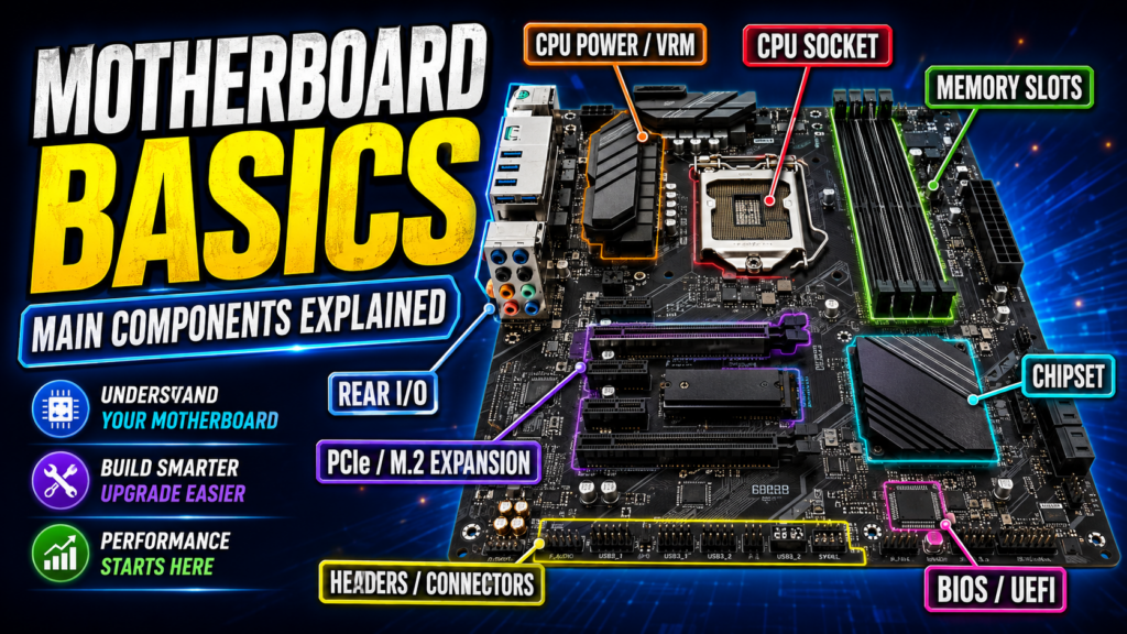
Its surface is covered with chips, slots, connectors, pins, capacitors, inductors, resistors, heatsinks, and countless tiny electronic components. To someone seeing a motherboard for the first time, it can be difficult to understand where to begin.
However, a motherboard is not as mysterious as it appears.
You can think of it as the central transportation and communication system of a computer.
The CPU, memory, graphics card, solid-state drives, hard drives, network adapters, audio devices, and external peripherals all use the motherboard to exchange data and receive power.
The motherboard usually does not perform most of the computer’s calculations itself. Instead, it provides power delivery, communication pathways, expansion interfaces, timing signals, and operating rules for the other components.
Without a motherboard, even the fastest CPU, the largest amount of memory, and the most powerful graphics card could not function together as a complete computer.
In this article, we will use the MSI MEG Z790 GODLIKE MAX as an example and examine the basic structure of a modern desktop computer motherboard.
By the end, you should be able to look at an unfamiliar motherboard and identify the purpose of its major regions.
1. Motherboards and Development Boards Are Not the Same
Before examining the motherboard itself, we should distinguish between two terms that are often confused.
A computer motherboard is designed to connect the CPU, memory, graphics card, storage devices, power supply, and peripheral interfaces into a complete personal computer.
A development board is designed mainly for learning, experimentation, software development, hardware debugging, embedded-system design, and product prototyping.
Common development boards include:
- Arduino boards
- STM32 boards
- ESP32 boards
- Raspberry Pi single-board computers
- FPGA development boards
- RISC-V development boards
A typical development board may include a main processor or microcontroller, Flash memory, RAM, a clock circuit, a reset circuit, GPIO pins, power regulation, and debugging interfaces such as UART, I²C, SPI, JTAG, or SWD.
A desktop motherboard has a different purpose.
It is built to support standardized computer components such as desktop processors, DIMM memory modules, graphics cards, NVMe SSDs, SATA drives, USB devices, and expansion cards.
Both are printed circuit boards, but their intended use, architecture, and expansion methods are different.
This article focuses on desktop computer motherboards.
2. Why Does a Motherboard Look So Complicated?
The foundation of a motherboard is a printed circuit board, commonly called a PCB.
The visible lines on the surface represent only a small portion of the electrical connections. Most of the copper traces that carry power and data are hidden inside the board.
A modern high-end motherboard is built from multiple layers of copper and insulating material.
Different layers may be used for:
- Power distribution
- Ground planes
- High-speed data signals
- Memory signals
- Clock signals
- Low-speed control signals
The motherboard also contains many chips, capacitors, resistors, inductors, connectors, sockets, and protection components.
Together, these parts handle power conversion, data transmission, timing, device detection, temperature monitoring, and system control.
Many modern motherboards are also covered by metal heatsinks and decorative panels.
These components are not used only for appearance. Heatsinks help cool the CPU voltage regulator modules, chipset, and M.2 solid-state drives.
A typical desktop motherboard can be divided into several major areas:
- Rear I/O area
- CPU socket area
- CPU power delivery area
- Memory area
- High-speed expansion area
- Chipset area
- Internal connector and header area
- BIOS and UEFI-related components
Understanding these regions makes the motherboard much easier to analyze.
3. The Rear I/O Area
The rear input and output area is one of the most familiar parts of a motherboard.
After the motherboard is installed in a computer case, these ports appear at the back of the computer.
The rear I/O panel may include:
- USB Type-A ports
- USB Type-C ports
- Ethernet ports
- Audio connectors
- HDMI or DisplayPort outputs
- Wi-Fi antenna connectors
- Thunderbolt ports
- Optical audio outputs
- BIOS update buttons
- Clear CMOS buttons
Keyboards, mice, printers, microphones, speakers, external storage devices, and other USB peripherals connect through this area.
Some motherboards include HDMI or DisplayPort connectors. However, these video outputs normally require a processor with integrated graphics.
When a dedicated graphics card is installed, the monitor should usually be connected directly to the graphics card rather than to the motherboard.
Motherboards with built-in Wi-Fi and Bluetooth also provide antenna connectors.
The external antennas should be installed even if wireless communication appears to work without them. Without the antennas, Wi-Fi and Bluetooth signal strength, range, and stability may be significantly reduced.
The number and type of rear I/O ports vary greatly between motherboard models.
A high-end board may include Thunderbolt, multiple high-speed USB ports, 10-gigabit Ethernet, optical audio, and advanced wireless networking. A budget motherboard may provide only the most common interfaces.
The MSI MEG Z790 GODLIKE MAX, for example, includes multiple USB ports, USB Type-C, Thunderbolt 4, dual Ethernet connections, wireless antenna connectors, and audio interfaces.
4. The CPU Socket and Processor Area
The CPU is the primary computing engine of the system.
It executes software instructions, performs arithmetic operations, makes logical decisions, moves data, and controls many system functions.
Because of this, the CPU socket is one of the most important parts of the motherboard.
The socket creates the electrical and mechanical connection between the processor and the motherboard.
Different CPU families use different sockets.
A processor cannot be installed simply because it looks similar to another processor. The socket design, pin arrangement, electrical interface, firmware support, and chipset compatibility must all match.
The Z790 platform used in our example is based on Intel’s LGA 1700 socket and supports selected 12th-, 13th-, and 14th-generation Intel Core processors, depending on the motherboard model and BIOS version.
LGA stands for Land Grid Array.
With an LGA socket, the contact pins are located inside the motherboard socket, while the bottom of the CPU contains flat contact pads.
The processor must be installed in the correct orientation.
The CPU and socket normally include alignment notches and a small triangle marking. These indicators must be matched before the processor is lowered into place.
Using force or installing the CPU in the wrong direction can bend the socket pins and permanently damage the motherboard.
Before purchasing a motherboard, always verify:
- CPU socket compatibility
- Chipset compatibility
- BIOS support
- Processor generation support
- Power requirements
Matching the processor and motherboard is the first step in building a stable computer.
5. How CPU Power Delivery Works
Near the CPU socket, you will normally find one or two eight-pin CPU power connectors.
These connectors receive 12-volt power from the computer’s power supply.
However, the CPU cores operate at much lower voltages and require extremely precise power regulation.
The 12-volt input cannot be sent directly to the processor.
The components surrounding the CPU socket form the voltage regulator module, commonly called the VRM.
A VRM usually includes:
- A PWM controller
- Power stages or MOSFETs
- Inductors
- Capacitors
- Monitoring and protection circuits
The VRM converts the incoming 12-volt supply into the lower voltages required by the CPU.
It also supplies very large amounts of current while keeping the output voltage stable.
You can think of the VRM as a dedicated power conversion station for the processor.
When the CPU is idle, the power delivery system reduces its output.
When the CPU enters a heavy workload, the VRM must rapidly increase current while minimizing voltage fluctuations.
Modern high-performance processors can draw a great deal of current. For this reason, motherboards often use multiphase VRM designs.
Instead of forcing a single power stage to handle the entire load, multiple phases share the work. This can reduce stress on individual components, improve efficiency, distribute heat, and help maintain voltage stability.
However, the advertised number of power phases does not tell the whole story.
Motherboard quality also depends on:
- Power stage current ratings
- Controller design
- VRM cooling
- PCB quality
- Thermal performance
- Firmware tuning
- Real-world testing
The MSI MEG Z790 GODLIKE MAX uses a high-end power delivery design intended for powerful processors and demanding workloads.
Most users do not need such an extreme VRM.
A motherboard only needs to provide stable and adequate power for the processor that will actually be installed.
6. The Memory Slot Area
The CPU constantly reads instructions and data while programs are running.
Storage devices such as SSDs and hard drives are too slow to serve as the CPU’s immediate working memory.
For this reason, computers use RAM to temporarily hold active programs and data.
RAM can be understood as the CPU’s short-term workspace.
Unlike SSDs and hard drives, normal system memory is volatile. Its contents are usually lost when power is removed.
On most desktop motherboards, the memory slots are located to the right of the CPU socket.
Standard ATX motherboards often provide four DIMM slots, while smaller boards may provide only two.
DDR4 and DDR5 memory are not interchangeable.
They use different electrical standards, signaling methods, operating voltages, and notch positions.
Before purchasing memory, confirm whether the motherboard supports DDR4 or DDR5.
The MSI motherboard used in this example provides four DDR5 memory slots.
Motherboard manufacturers may advertise very high overclocked memory speeds. However, the maximum advertised speed is not guaranteed with every processor, memory kit, or slot configuration.
Actual memory stability depends on several factors:
- The CPU’s memory controller
- The number of memory modules
- Memory chip quality
- Module capacity
- Motherboard trace design
- BIOS version
- Memory timings
- Operating voltage
On a four-slot motherboard, a single memory module is often installed in slot A2.
When two modules are used, they are commonly installed in slots A2 and B2 to enable dual-channel operation.
The correct slots can vary, so the motherboard manual should always be consulted.
Memory slots are placed close to the CPU because the memory bus carries large amounts of high-speed parallel data.
You may also notice that some memory traces have curved or serpentine shapes.
These shapes are not decorative.
They are used to adjust trace lengths so that related signals reach their destination at nearly the same time. This is known as length matching.
7. PCI Express and M.2 Expansion Areas
Below the CPU area, we normally find the high-speed expansion section.
The most visible parts are the long PCI Express slots.
The top full-length slot is commonly used for a dedicated graphics card.
Other PCI Express slots may support:
- Network cards
- Audio cards
- Video capture cards
- Storage controllers
- Accelerator cards
- USB expansion cards
- Specialized computing devices
PCI Express is often abbreviated as PCIe.
A PCIe connection is described by both its generation and its lane count.
For example, PCIe 5.0 x16 means:
- Fifth-generation PCI Express
- Sixteen data lanes
A newer PCIe generation provides more bandwidth per lane.
A larger lane count provides more total bandwidth.
For example, a PCIe 4.0 x4 interface provides a theoretical one-direction payload bandwidth of roughly 7.9 gigabytes per second.
A PCIe 5.0 x16 interface provides a theoretical one-direction payload bandwidth of roughly 63 gigabytes per second.
These figures describe theoretical interface capacity. They do not guarantee that a real device will achieve the same transfer speed in every workload.
The expansion area also contains M.2 slots.
M.2 slots are commonly used for NVMe solid-state drives.
Some M.2 slots connect directly to the CPU, while others connect through the chipset.
A CPU-connected M.2 slot normally has a shorter data path and may provide lower latency.
A chipset-connected slot still offers high performance, but its traffic shares the chipset’s connection to the processor with other devices.
PCI Express lanes are limited resources.
Installing an M.2 drive in a particular slot may reduce the lane count of another PCIe slot, disable a SATA connector, or change the operating mode of another interface.
This is known as lane sharing or resource sharing.
Before installing several expansion cards and multiple NVMe drives, check the motherboard manual and lane-sharing table.
8. The Chipset Area
Older computer architectures commonly used two major support chips known as the northbridge and southbridge.
The northbridge handled communication between the CPU, memory, and high-speed graphics interface.
The southbridge handled lower-speed devices such as USB, SATA, audio, and other peripherals.
Modern processors have absorbed many of the functions once performed by the northbridge.
The memory controller and primary PCI Express controller are now usually integrated directly into the CPU.
As a result, the traditional northbridge has largely disappeared.
The major support chip located near the lower-right portion of a modern Intel motherboard is more accurately called the chipset or Platform Controller Hub, abbreviated as PCH.
The chipset can be understood as an interface expansion center.
The CPU reserves its most valuable direct high-speed connections for components such as the graphics card and primary NVMe drive.
The chipset expands the system with additional:
- USB ports
- SATA ports
- PCI Express lanes
- Network controllers
- Audio functions
- Storage interfaces
- Peripheral connections
The chipset communicates with the CPU through a dedicated link.
On the Intel Z790 platform, this connection is based on DMI 4.0.
The chipset defines the maximum number and type of resources available to the motherboard designer.
However, a motherboard manufacturer does not have to expose every chipset resource as a physical connector.
Every additional controller, slot, high-speed port, or storage interface increases design complexity, PCB routing requirements, cooling demands, and manufacturing cost.
This is why two motherboards using the same chipset can have very different features and prices.
The chipset defines the platform’s expansion potential.
The motherboard manufacturer decides how to use that potential.
9. Internal Headers and Edge Connectors
Along the bottom and right edges of the motherboard, you will find many small pins and connectors.
These are commonly called headers.
Headers connect the motherboard to the computer case, cooling system, lighting system, and front-panel ports.
Front Audio Header
The front audio header connects the headphone and microphone ports on the front of the computer case.
Without this connection, the case’s front audio ports will not work.
RGB and ARGB Headers
Modern motherboards commonly provide two lighting standards.
A 12-volt four-pin RGB header normally controls all connected LEDs as a single group. The LEDs usually display the same color at the same time.
A 5-volt three-pin addressable RGB header, often called ARGB, can control individual LEDs and create effects such as waves, gradients, and moving patterns.
These headers use different voltages and pin layouts.
They must not be mixed.
Connecting a 5-volt ARGB device to a 12-volt RGB header may damage the lighting device.
Fan and Pump Headers
Fan and pump headers provide power and speed-control signals.
The CPU cooler fan should normally be connected to the CPU_FAN header.
A liquid-cooling pump should be connected according to the cooler and motherboard instructions, often using a dedicated PUMP header.
The motherboard can monitor fan speed and adjust cooling performance based on temperature.
Internal USB Headers
Internal USB headers connect the motherboard to the USB ports on the front of the computer case.
Different headers may support:
- USB 2.0
- USB 3.x Type-A ports
- Front-panel USB Type-C
These connectors are not interchangeable.
Front-Panel Header
The front-panel header connects the case’s:
- Power button
- Reset button
- Power LED
- Drive activity LED
The pins are small and easy to connect incorrectly.
Always refer to the motherboard manual during installation.
SATA Connectors
SATA connectors are used for:
- Mechanical hard drives
- 2.5-inch SATA SSDs
- Optical drives
- Some storage accessories
24-Pin Main Power Connector
The large 24-pin connector along the right edge is the motherboard’s primary power input.
It supplies power to many motherboard circuits and devices.
Diagnostic Displays and LEDs
High-end motherboards may include two-digit diagnostic code displays and status LEDs.
If the computer fails to start, these indicators can help determine whether the problem is related to:
- CPU
- Memory
- Graphics card
- Boot device
Diagnostic features can save a great deal of time during system assembly and troubleshooting.
10. Other Control Chips on the Motherboard
A motherboard contains far more than the CPU socket and chipset.
Many smaller control chips are distributed across the board.
The lower-left area often contains the audio codec.
The codec converts digital audio data into analog signals that headphones and speakers can use.
It also converts microphone input into digital data.
Other motherboard controllers may include:
- Ethernet controllers
- Wi-Fi and Bluetooth controllers
- USB controllers
- Clock generators
- Temperature monitoring chips
- Fan controllers
- Super I/O controllers
- PCI Express switches
- Signal redrivers
- Storage controllers
Some advanced interfaces require third-party controllers because the chipset cannot provide every function directly.
For example, additional high-speed networking, Thunderbolt, extra USB ports, or specialized storage features may require separate controller chips.
A motherboard is therefore not controlled by a single chip.
It is a coordinated system of processors, controllers, power circuits, firmware, sensors, and communication links.
11. What Do ATX, Micro ATX, Mini ITX, and E-ATX Mean?
Motherboards are manufactured in several standard sizes, known as form factors.
Common form factors include:
- ATX
- Micro ATX
- Mini ITX
- E-ATX
The motherboard form factor determines whether the board can physically fit inside a particular computer case.
A compact case may not support a full-size ATX or E-ATX motherboard.
Form factor also affects the amount of physical space available for:
- Memory slots
- PCI Express slots
- M.2 drives
- Power delivery components
- Internal headers
- Storage connectors
- Additional controllers
However, a smaller motherboard is not necessarily slower or lower quality.
A high-end Mini ITX motherboard may still provide strong CPU power delivery, fast networking, premium audio, and multiple high-speed storage interfaces.
The main limitation is physical expansion space.
Motherboard size should therefore be selected according to the computer case, required expansion cards, cooling system, and number of storage devices.
12. What Are BIOS and UEFI?
The motherboard requires firmware to initialize and manage the hardware.
Traditionally, this firmware was called the BIOS, which stands for Basic Input/Output System.
Modern motherboards generally use UEFI, or Unified Extensible Firmware Interface.
However, many people still use the word BIOS when referring to the motherboard firmware and its settings interface.
When the power button is pressed, the CPU does not immediately begin running Windows or Linux.
The motherboard firmware first initializes and checks essential hardware, including:
- CPU
- Memory
- Graphics hardware
- Storage controllers
- USB devices
- Cooling systems
This early testing and initialization process is commonly associated with POST, or Power-On Self-Test.
If the basic hardware is working, the firmware searches for a bootable device and transfers control to the operating system’s bootloader.
The BIOS or UEFI settings interface allows users to configure:
- Boot order
- Fan curves
- CPU settings
- Memory settings
- Storage modes
- Security options
- Virtualization features
- Integrated devices
- Power management
On supported systems, users may enable an XMP memory profile to apply preconfigured memory speed and timing settings.
Incorrect settings can sometimes prevent the computer from booting.
In that situation, the firmware settings can often be reset by clearing the CMOS.
Depending on the motherboard, this may involve:
- Pressing a Clear CMOS button
- Shorting a specified pair of pins
- Temporarily removing the coin-cell battery
High-end motherboards may provide a BIOS Flashback feature that allows the firmware to be updated without entering the operating system.
Firmware updates may:
- Fix compatibility problems
- Improve memory support
- Correct security vulnerabilities
- Repair firmware bugs
- Add support for newer processors
BIOS updates must be performed carefully.
Power should not be interrupted during the update, and the manufacturer’s instructions should be followed exactly.
13. How to Choose the Right Motherboard
After understanding the basic structure of a motherboard, the next question is how to choose one.
Most users should consider five major factors.
1. CPU Compatibility
The motherboard must support the processor you plan to use.
Do not check only the physical socket.
Also verify:
- Chipset support
- CPU support list
- Required BIOS version
- Power requirements
A processor may physically fit the socket but still require a newer BIOS version.
2. Motherboard Form Factor
Make sure the motherboard fits inside the computer case.
Check whether the case supports:
- ATX
- Micro ATX
- Mini ITX
- E-ATX
The form factor also affects expansion capacity.
3. CPU Power Delivery and Cooling
A low-power or midrange processor normally does not require an extreme VRM.
A high-power processor used for rendering, scientific workloads, continuous compilation, or overclocking may benefit from stronger power delivery and larger heatsinks.
Choose a motherboard that can support the processor under sustained workloads.
4. Memory Support
Check whether the motherboard supports DDR4 or DDR5.
Also examine:
- Number of memory slots
- Maximum memory capacity
- Supported memory speeds
- Memory compatibility list
- Recommended slot configuration
Do not assume that every memory kit will operate at its advertised overclocked speed.
5. Expansion and Connectivity
Check whether the motherboard provides enough:
- PCI Express slots
- M.2 slots
- SATA connectors
- USB ports
- Network ports
- Wireless connectivity
- Fan headers
- Front-panel connectors
- Display outputs
Do not choose a motherboard only by its chipset name or appearance.
Two motherboards using the same Z790, B760, or other chipset may differ significantly in power delivery, connectivity, cooling, expansion slots, and additional controllers.
The most reliable method is to open the official specification page and motherboard manual, then compare each feature with your actual requirements.
Conclusion
A computer motherboard looks complicated because it combines power delivery, communication, storage, expansion, control, and firmware into a single platform.
Once the motherboard is divided into functional regions, its structure becomes much easier to understand.
The rear I/O area connects keyboards, mice, networks, audio devices, displays, and external peripherals.
The center of the board contains the CPU socket and CPU power delivery system.
The memory slots are located close to the processor.
The lower area contains PCI Express slots and M.2 storage connections.
The chipset expands USB, SATA, PCI Express, and other peripheral resources.
The edges of the board contain power connectors, fan headers, lighting headers, USB headers, front-panel connectors, and audio connections.
BIOS or UEFI firmware initializes the hardware and prepares the system to load an operating system.
The motherboard is not usually the fastest computing component in a computer.
However, it is the foundation that allows all other components to work together.
It provides power to the processor, communication pathways for memory and graphics, interfaces for storage and peripherals, and the firmware required to start the system.
The next time you look at a motherboard, you will no longer see a random collection of chips, slots, and connectors.
You will see a complete system made of power, processing, memory, storage, communication, control, and expansion modules.
Important Note
This article uses the MSI MEG Z790 GODLIKE MAX as a structural example.
Motherboards from different manufacturers, chipset families, processor platforms, and form factors may have significantly different layouts, power designs, lane-sharing rules, connector positions, and expansion capabilities.
Before installing a CPU, memory module, power cable, storage device, cooling system, or front-panel connector, always consult the official manual for the exact motherboard model.