How Adders Work
How Computers Add Binary Numbers Using Logic Gates
Chapter 1 — Introduction
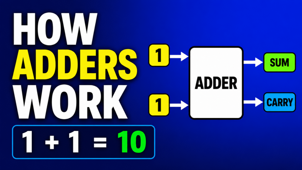
How does a computer add two numbers?
When you type:
Five plus three,
the computer instantly produces the answer:
Eight.
This looks simple.
But inside the processor, there are no tiny people doing arithmetic.
There are no mechanical calculators.
And the CPU does not understand numbers in the same way humans do.
A computer works with electrical signals.
A low voltage represents zero.
A high voltage represents one.
Using only these two states, computers can represent numbers, instructions, text, images, video, and sound.
But representing numbers is only the beginning.
The computer must also perform calculations with them.
To do that, it uses special digital circuits called adders.
Adders are built from logic gates.
Logic gates are built from transistors.
And large collections of adders become part of the arithmetic logic unit inside the CPU.
In this video, we will follow the complete path:
Binary numbers.
Binary addition.
Logic gates.
Half adders.
Full adders.
Multi-bit adders.
Fast carry systems.
Subtraction.
Overflow.
And finally, the role of adders inside a real processor.
By the end of this video, you will understand how computers perform arithmetic using only zeros, ones, and logic gates.
Chapter 2 — Why Addition Is So Important
Addition is one of the most important operations inside a computer.
It is not only used when you open a calculator and add two numbers.
The processor also uses addition to calculate memory addresses.
It uses addition to move through instructions.
It uses addition to update the program counter.
It uses addition to access elements in an array.
It uses addition to change the stack pointer.
It uses addition during multiplication.
And it can even use addition to perform subtraction.
Suppose a processor wants to read the next instruction.
If the current instruction address is:
One thousand,
and each instruction is four bytes long,
the processor may calculate:
One thousand plus four.
The result is the address of the next instruction.
This means that even when a program does not appear to be performing arithmetic, addition may still be happening inside the CPU.
That is why adders are fundamental parts of digital systems.
Chapter 3 — Understanding Binary Numbers
Humans normally use the decimal number system.
Decimal uses ten digits:
Zero through nine.
Each position represents a power of ten.
For example, the decimal number 325 means:
Three hundreds.
Two tens.
And five ones.
Computers normally use binary.
Binary has only two digits:
Zero and one.
Each position represents a power of two.
From right to left, the positions are:
One.
Two.
Four.
Eight.
Sixteen.
Thirty-two.
And so on.
Consider the binary number:
One zero one one.
The rightmost one represents one.
The next one represents two.
The zero represents zero groups of four.
And the leftmost one represents eight.
So:
Eight plus zero plus two plus one equals eleven.
Therefore:
Binary one zero one one represents decimal eleven.
Binary numbers may look unfamiliar at first.
But the arithmetic follows simple and predictable rules.
Chapter 4 — The Rules of Binary Addition
Decimal addition has many possible digit combinations.
Binary addition has only four basic cases.
The first rule is:
Zero plus zero equals zero.
There is no carry.
The second rule is:
Zero plus one equals one.
There is no carry.
The third rule is:
One plus zero equals one.
Again, there is no carry.
The fourth rule is:
One plus one equals binary one zero.
This is the most important case.
In binary, the number two is written as:
One zero.
So when we add one plus one, the result has two parts.
The sum bit is zero.
And the carry bit is one.
This is similar to decimal addition.
When we add nine plus one, we write zero in the current column and carry one into the next column.
Binary addition follows the same idea.
But because binary has only two digits, carrying happens more frequently.
There is also another important case:
One plus one plus one.
This happens when two input bits and an incoming carry are all equal to one.
The decimal result is three.
Binary three is written as:
One one.
So the sum bit is one.
And the carry bit is also one.
These simple rules are enough to build a hardware circuit that performs addition.
Chapter 5 — The Logic Gates We Need
To build an adder, we first need logic gates.
The most important gates for basic addition are:
The XOR gate.
The AND gate.
And later, the OR gate.
An XOR gate produces one when its two inputs are different.
If the inputs are zero and zero, the output is zero.
If the inputs are zero and one, the output is one.
If the inputs are one and zero, the output is one.
If the inputs are one and one, the output is zero.
Now compare this behavior with the sum bit from binary addition.
Zero plus zero produces a sum of zero.
Zero plus one produces a sum of one.
One plus zero produces a sum of one.
One plus one produces a sum of zero, with a separate carry.
This means the XOR gate produces exactly the correct sum bit when adding two single binary digits.
The AND gate produces one only when both inputs are one.
That is exactly when one plus one creates a carry.
So the XOR gate can calculate the sum.
And the AND gate can calculate the carry.
Together, these two gates form a half adder.
Chapter 6 — What Is a Half Adder?
A half adder is a small digital circuit that adds two one-bit binary numbers.
It has two inputs.
Input A.
And input B.
It also has two outputs.
The Sum output.
And the Carry output.
The Sum output is calculated using an XOR gate.
Sum equals:
A XOR B.
The Carry output is calculated using an AND gate.
Carry equals:
A AND B.
Let us test every possible input combination.
When A is zero and B is zero:
The sum is zero.
The carry is zero.
When A is zero and B is one:
The sum is one.
The carry is zero.
When A is one and B is zero:
The sum is one.
The carry is zero.
When A is one and B is one:
The sum is zero.
The carry is one.
The half adder correctly implements all four basic cases of adding two binary digits.
It is one of the simplest arithmetic circuits in digital electronics.
Chapter 7 — Why It Is Called a Half Adder
The name half adder can be confusing.
It does not mean that the circuit produces half of the correct answer.
It means that the circuit handles only part of the complete addition problem.
A half adder can add two input bits.
But it cannot accept a carry from a previous column.
This is not a problem when adding only the rightmost bits of two binary numbers.
The rightmost column usually has no incoming carry.
But in every column after that, an incoming carry may exist.
Consider this addition:
One one.
Plus zero one.
Starting from the right:
One plus one produces zero, with a carry of one.
Now move to the next column.
The next calculation is not simply:
One plus zero.
It is:
One plus zero plus the incoming carry of one.
A half adder has only two inputs.
It cannot handle all three values.
To solve this problem, we need a full adder.
Chapter 8 — What Is a Full Adder?
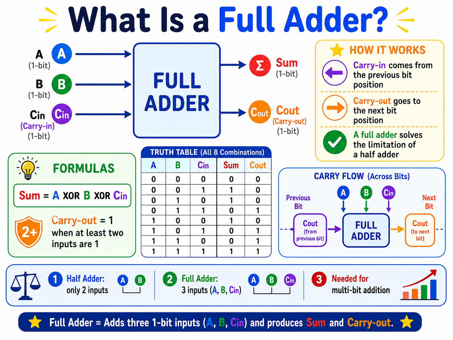
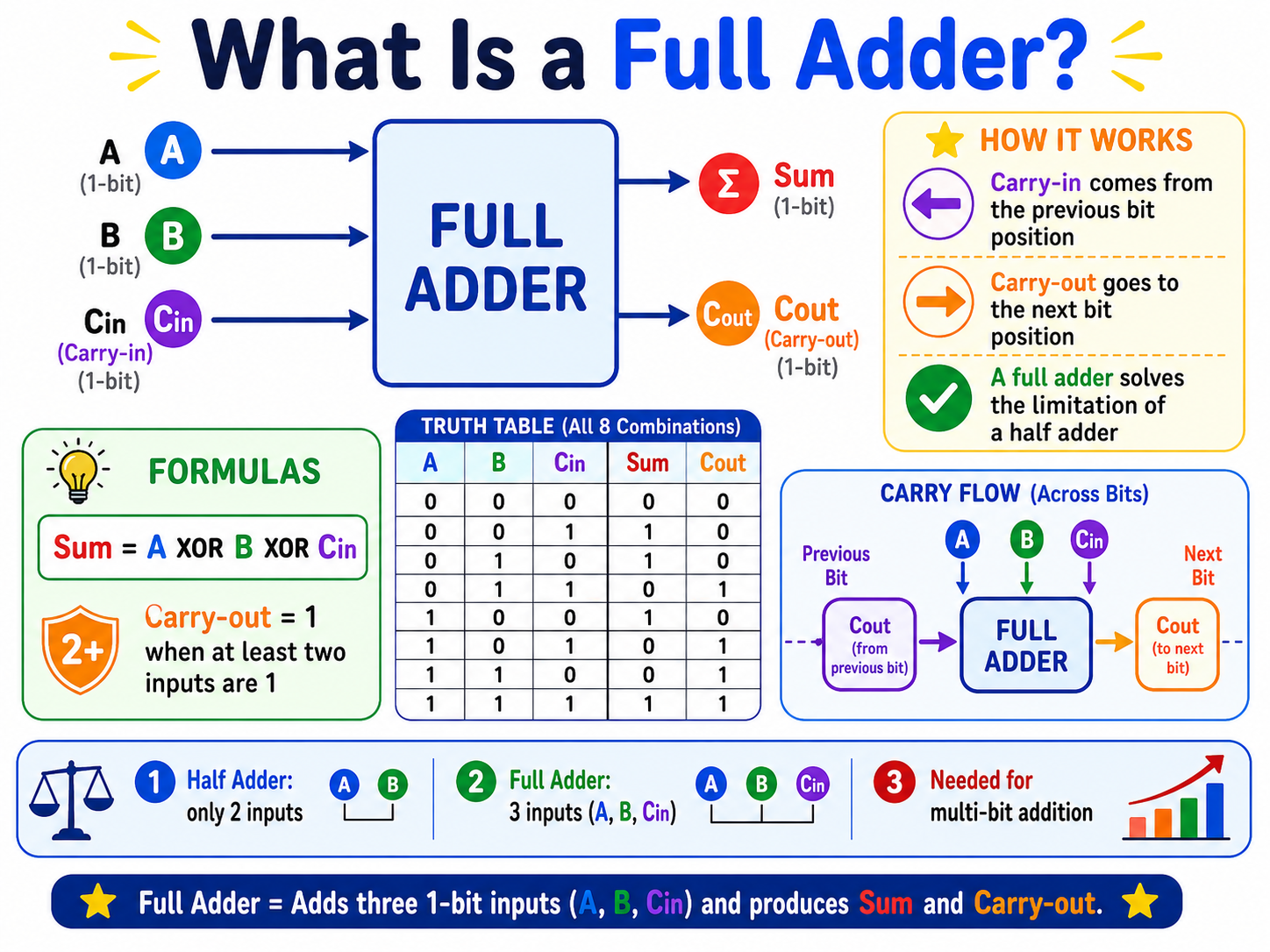
A full adder adds three one-bit inputs.
They are:
Input A.
Input B.
And Carry-in.
Carry-in is usually written as C in.
It comes from the previous, less significant bit position.
The full adder produces two outputs.
Sum.
And Carry-out.
Carry-out is usually written as C out.
The Sum output tells us the result for the current bit position.
The Carry-out travels into the next, more significant bit position.
The Sum equation is:
A XOR B XOR Carry-in.
The Carry-out becomes one when at least two of the three inputs are one.
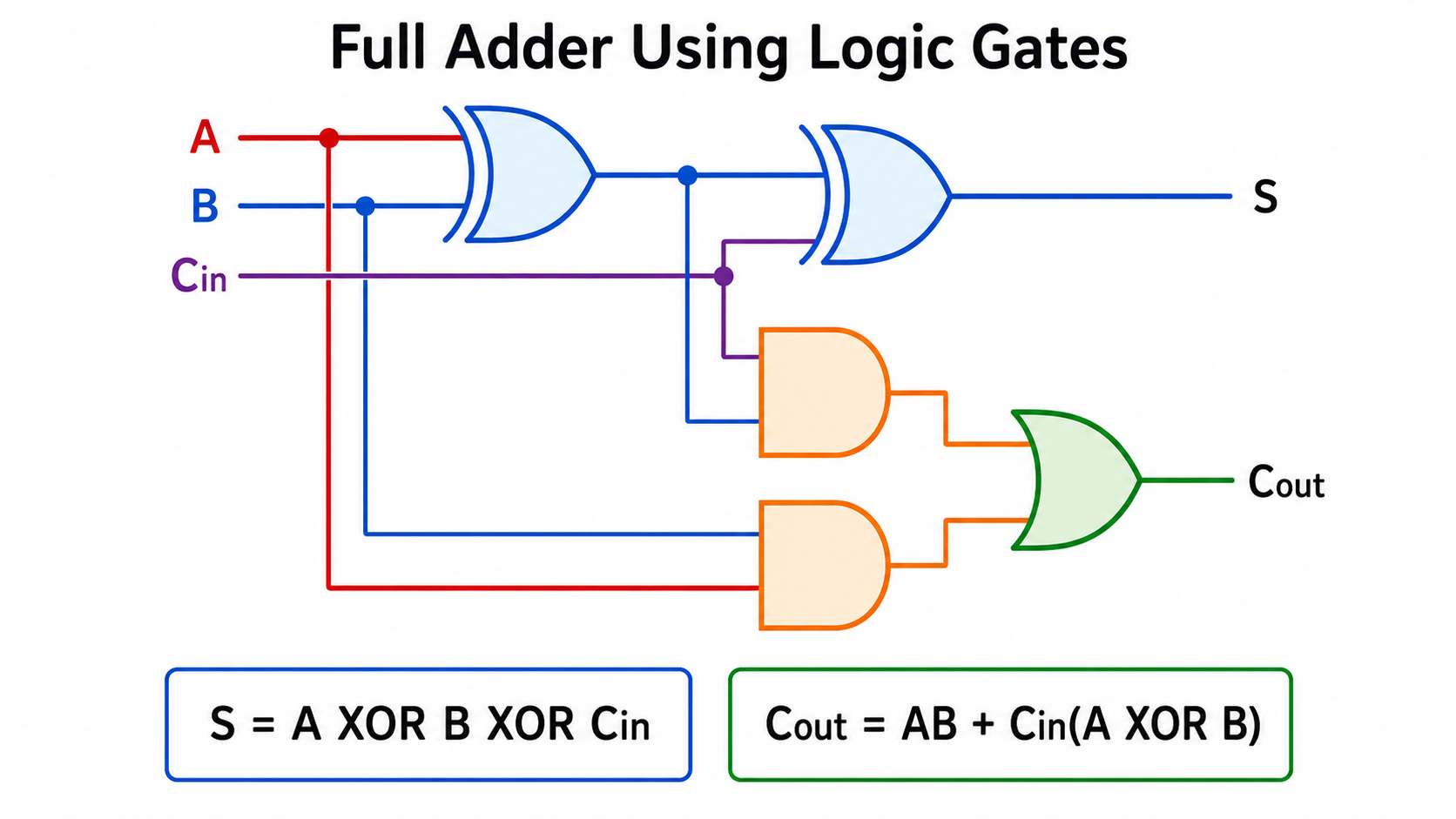
For example:
If A and B are both one, a carry is produced.
If A and Carry-in are both one, a carry is produced.
If B and Carry-in are both one, a carry is produced.
If all three inputs are one, the sum is one and the carry is also one.
A full adder therefore solves the limitation of the half adder.
It can process both the current input bits and a carry from the previous column.
Chapter 9 — Building a Full Adder from Half Adders
A full adder can be constructed using two half adders and one OR gate.
First, the first half adder receives inputs A and B.
It produces an intermediate sum.
Let us call it S1.
It also produces the first carry.
Let us call it C1.
The intermediate sum is:
A XOR B.
The first carry is:
A AND B.
Next, the second half adder receives:
S1.
And Carry-in.
It produces the final Sum output.
It also produces a second carry.
Let us call it C2.
The final Sum is:
S1 XOR Carry-in.
The second carry is:
S1 AND Carry-in.
Finally, the OR gate combines C1 and C2.
Carry-out equals:
C1 OR C2.
Why do we use an OR gate?
Because a carry may be generated in either stage.
If A and B are both one, the first half adder generates a carry.
If the intermediate sum and Carry-in are both one, the second half adder generates a carry.
If either condition occurs, the full adder must produce Carry-out equal to one.
This structure shows how larger digital circuits can be built from smaller reusable components.
Logic gates form half adders.
Half adders form full adders.
And full adders form multi-bit adders.
Chapter 10 — The Full Adder Truth Table
A full adder has three inputs.
Each input can be zero or one.
This creates eight possible input combinations.
When all three inputs are zero:
The sum is zero.
The carry-out is zero.
When only one input is one:
The sum is one.
The carry-out is zero.
This happens because the total value is one.
When exactly two inputs are one:
The total value is two.
Binary two is one zero.
So the sum is zero.
And the carry-out is one.
When all three inputs are one:
The total value is three.
Binary three is one one.
So the sum is one.
And the carry-out is one.
This gives us an easy way to understand the full adder.
The Sum output is one when an odd number of inputs are one.
The Carry-out is one when at least two inputs are one.
These rules are implemented entirely with logic gates.
Chapter 11 — Building a Multi-Bit Adder
A single full adder processes only one bit position.
But computers usually work with larger binary numbers.
They may use:
Eight-bit numbers.
Sixteen-bit numbers.
Thirty-two-bit numbers.
Sixty-four-bit numbers.
Or even larger values.
To add multi-bit numbers, we connect several full adders together.
Each full adder handles one bit position.
The Carry-out from one stage becomes the Carry-in of the next stage.
This arrangement is called a ripple-carry adder.
Imagine a four-bit adder.
It has four stages.
The first stage adds the least significant bits.
Its Carry-out enters the second stage.
The second stage produces another Carry-out.
That carry enters the third stage.
And the process continues until the most significant bit is reached.
The carry appears to ripple from right to left through the circuit.
That is where the name ripple-carry adder comes from.
Chapter 12 — A Four-Bit Addition Example
Let us add two four-bit binary numbers.
Zero one zero one.
Plus zero zero one one.
In decimal, these numbers are five and three.
The correct result should be eight.
In four-bit binary, eight is:
One zero zero zero.
Start with the rightmost column.
One plus one equals binary one zero.
Write zero as the sum bit.
Carry one into the next column.
Now the second column contains:
Zero plus one plus Carry-in one.
The total is two.
Write zero.
Carry one.
The third column contains:
One plus zero plus Carry-in one.
Again, the total is two.
Write zero.
Carry one.
The fourth column contains:
Zero plus zero plus Carry-in one.
The result is one.
There is no new carry.
The final answer is:
One zero zero zero.
This is decimal eight.
Inside a ripple-carry adder, four connected adder stages perform these same operations using electrical signals.
Chapter 13 — The Ripple-Carry Delay
Ripple-carry adders are simple.
But they have an important weakness.
The final result cannot always be known immediately.
Each stage may need to wait for the carry from the previous stage.
Consider a long addition in which a carry begins at the least significant bit.
That carry may need to travel through every stage before the final output becomes correct.
In a four-bit adder, this delay may be small.
But in a sixty-four-bit adder, the carry may pass through many logic gates.
Each logic gate requires a small amount of time to respond.
The delay of one gate is extremely short.
But when many delays are connected in sequence, they add together.
The processor must allow enough time for the complete result to stabilize before storing it in a register.
This is called propagation delay.
Propagation delay limits how fast a circuit can operate.
As processors became faster, engineers developed more advanced adder designs.
Chapter 14 — Faster Adders
One faster design is the carry-lookahead adder.
Instead of waiting for the carry to ripple through every stage, the circuit predicts carry values using additional logic.
For each bit position, the circuit determines whether that position will generate a carry.
A bit position generates a carry when both input bits are one.
The circuit also determines whether that position will propagate an incoming carry.
A carry is propagated when the input combination allows Carry-in to pass to Carry-out.
Using these generate and propagate signals, the circuit can calculate several carry values in parallel.
This reduces the time required to obtain the final result.
Other high-performance designs include:
Carry-select adders.
Carry-skip adders.
And parallel-prefix adders.
Examples of parallel-prefix structures include the Kogge-Stone adder and the Brent-Kung adder.
These circuits use more gates and more wiring.
But they can produce results faster than a simple ripple-carry adder.
Modern processors choose adder designs based on several trade-offs:
Speed.
Power consumption.
Chip area.
Circuit complexity.
And manufacturing cost.
A simple embedded processor may use a relatively small adder.
A high-performance CPU may use a much faster and more complex structure.
Chapter 15 — How Adders Perform Subtraction
An adder can also be used to subtract numbers.
This is possible because computers usually represent negative binary numbers using two’s complement.
To calculate:
A minus B,
the processor can calculate:
A plus the two’s complement of B.
The two’s complement of a binary number is created in two steps.
First, invert every bit.
Change zero to one.
And change one to zero.
Then add one.
For example, suppose we want to calculate five minus three using four bits.
Five is:
Zero one zero one.
Three is:
Zero zero one one.
First, invert the bits of three.
The result is:
One one zero zero.
Then add one.
The result is:
One one zero one.
This is the four-bit two’s-complement representation of negative three.
Now add it to five:
Zero one zero one.
Plus one one zero one.
The result is:
One zero zero one zero.
Because we are using four bits, the final carry is discarded.
The remaining result is:
Zero zero one zero.
This is decimal two.
So the same hardware used for addition can also perform subtraction.
In many arithmetic logic units, a control signal determines whether the second input should be used normally or inverted.
The subtraction control signal can also provide the initial Carry-in of one.
This lets one adder perform both addition and subtraction.
Chapter 16 — Carry and Overflow Are Not the Same
Carry and overflow are often confused.
But they describe different situations.
Carry is mainly important when working with unsigned binary numbers.
It indicates that the result requires an additional bit.
For example, consider four-bit unsigned addition:
One one one one.
Plus zero zero zero one.
The decimal calculation is:
Fifteen plus one equals sixteen.
But four bits can represent only values from zero to fifteen.
The four-bit result becomes:
Zero zero zero zero.
And a Carry-out of one is produced.
The carry tells us that the complete result requires a fifth bit.
Signed overflow is different.
It occurs when the result of a signed calculation cannot be represented using the available number of bits.
In four-bit two’s complement, the signed range is:
Negative eight through positive seven.
Consider:
Zero one one one.
Plus zero zero zero one.
This represents:
Seven plus one.
The binary result is:
One zero zero zero.
But in four-bit two’s complement, one zero zero zero represents negative eight.
Two positive numbers have incorrectly produced a negative result.
This means signed overflow has occurred.
A common rule is:
Signed overflow occurs when two numbers with the same sign are added, but the result has the opposite sign.
Processors often store carry and overflow in separate status flags.
Software can examine these flags when necessary.
Chapter 17 — Adders Inside the ALU
The arithmetic logic unit, or ALU, is the part of the processor that performs arithmetic and logical operations.
The ALU may perform operations such as:
Addition.
Subtraction.
AND.
OR.
XOR.
Bit shifting.
Comparison.
And sometimes multiplication or division.
The adder is one of the central components of the ALU.
Suppose an instruction says:
Add register one and register two.
The processor reads the values from the two registers.
It sends them into the ALU.
The ALU selects the addition operation.
The adder calculates the result.
The result is then written into a destination register.
The data path may look like this:
Register file.
To ALU.
To result bus.
Back to the register file.
The same adder may also help perform subtraction, address calculation, and comparisons.
For example, two values can be compared by subtracting one from the other and examining the result.
If the result is zero, the values are equal.
If the result is negative, one value may be smaller than the other, depending on whether the comparison is signed or unsigned.
The adder is therefore not an isolated calculator.
It is deeply integrated into the processor’s data path and control system.
Chapter 18 — Adders Beyond Arithmetic Instructions
Adders are used in many places throughout a processor.
The program counter uses an adder to calculate the address of the next instruction.
A load instruction may use an adder to combine a base address with an offset.
For example:
A register may contain the starting address of an array.
The instruction may contain an offset.
The adder combines them to find the required memory address.
The stack pointer may be increased or decreased when functions are called.
Branch instructions may calculate a target address by adding an offset to the current program counter.
Multiplication circuits may use repeated additions or more advanced partial-product adders.
Division circuits may also contain adders and subtractors.
Graphics processors use enormous numbers of arithmetic units to process many values in parallel.
Digital signal processors use adders for filters, audio processing, and communication systems.
Adders are everywhere in digital electronics.
Whenever a system must count, move through addresses, calculate a position, or combine numerical values, an adder may be involved.
Chapter 19 — From Transistors to Addition
Let us now connect the complete hierarchy.
At the lowest level, there are transistors.
A transistor can act as an electronic switch.
Transistors are combined to create logic gates.
Logic gates implement operations such as:
AND.
OR.
NOT.
And XOR.
XOR and AND gates can form a half adder.
Two half adders and an OR gate can form a full adder.
Multiple full adders can form a multi-bit adder.
Faster carry systems can improve performance.
The adder becomes part of the ALU.
The ALU becomes part of the processor data path.
The processor executes instructions from software.
So when a program calculates five plus three, the operation can ultimately be traced back through many layers:
Software.
Instructions.
Registers.
The ALU.
Adders.
Logic gates.
Transistors.
And electrical signals.
A complex calculation performed by modern software begins with simple physical switches turning on and off.
Conclusion
Computers do not understand arithmetic in the human sense.
They manipulate electrical signals that represent zeros and ones.
Binary addition follows four basic rules.
Zero plus zero equals zero.
Zero plus one equals one.
One plus zero equals one.
And one plus one produces a sum of zero with a carry of one.
An XOR gate calculates the sum of two input bits.
An AND gate calculates the carry.
Together, they form a half adder.
A full adder adds two input bits and an incoming carry.
Multiple full adders can be connected to add larger binary numbers.
A ripple-carry adder is simple, but the carry may take time to travel through the circuit.
Faster designs calculate carry information using parallel logic.
The same adder hardware can also perform subtraction using two’s complement.
And inside the CPU, adders are used for far more than calculator operations.
They update the program counter.
They calculate memory addresses.
They manage stack positions.
They perform comparisons.
And they form a central part of the arithmetic logic unit.
From transistors,
to logic gates,
to adders,
to the ALU,
to the CPU,
this is how computers perform arithmetic using only zeros and ones.
In our recent videos, we explored how computers are built from logic gates and adders.
In the next part of Gate & Kernel, we will return to Linux.
We will move from the circuits inside the processor to the operating system that manages the processor, memory, files, devices, and running programs.
Because understanding computers requires both sides:
The gates that perform the work.
And the kernel that controls the system.
Thank you for watching Gate & Kernel.