This article will start with the I-Type integer register instructions and provide a detailed introduction to each assembly instruction and its specific implementation.
1. I-type Integer Register-Immediate Instructions
I-Type – Immediate Type.
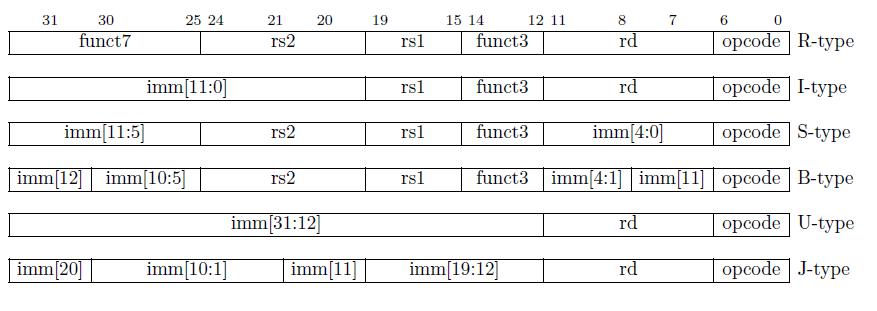
Apart from the CSR (Control and Status Register) instructions, all immediate values that appear are sign-extended and usually placed in the most significant bits (leftmost bit) that are available in the instruction.
All instruction types (I-type, S-type, B-type, U-type, and J-type) that use immediate values have their sign extension determined by bit 31 of the instruction (which is also the highest bit of the immediate value, such as imm[20] in J-type instructions).
Therefore, the immediate values mentioned in I-type instructions are all sign-extended.
Here is an example to explain sign extension. For instance, consider a 12-bit immediate value.
If the highest bit is 0, the immediate value is positive. If the highest bit is 1, the immediate value is negative. When sign-extending a positive immediate value, the upper 20 bits are filled with 0s. When sign-extending a negative immediate value, the upper 20 bits are filled with 1s. After sign extension, the immediate value can be added or compared with other operands.
On the other hand, when performing unsigned extension, the upper 20 bits are filled with 0s regardless of whether the immediate value is positive or negative.
For example, if the value of a signed 12-bit immediate is 0xF8C (i.e., the binary number 1111 1000 1100), it is a negative number with a sign bit of 1. When performing sign extension, we fill all the remaining bits with 1s, resulting in 0xFFFFF8C. This result is a 32-bit binary number that represents the sign-extended value of the signed immediate value.
Most integer arithmetic instructions operate on the XLEN bits stored in integer registers (corresponding to 32 bits in RV32I). Integer arithmetic instructions either use I-type instructions for register-immediate operations or use R-type instructions for register-register operations.
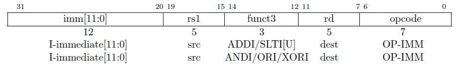
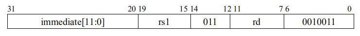
The opcode corresponding to I-type is named OP-IMM.
The immediate value corresponding to I-type instructions is fixed at 12 bits and is named I-immediate, as shown in Figure 2.
There are a total of 15 instructions in I-type category. We will introduce the first six instructions, which are:
- ADDI
- SLTI
- SLTIU
- ANDI
- ORI
- XORI
1.1. ADDI
ADD Immediate
The ADDI instruction format :
ADDI rd, rs1, immediate.
x[rd] = x[rs1] + sext(imm).
For example:
ADDI x13, x12, 5
This instruction adds the value in the x12 register to the sign-extended immediate value of 5, and stores the result in the x13 register.

- OP-IMM (0-6) : 001_0011
- funct3 (12-14) : 000
- immediate (20-31): 12’ b0000_0000_0101
- rs1 (15-19): 5’b0_1100
- rd (7-11): 5’b0_1101
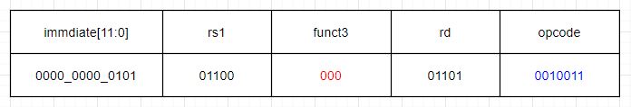
ADDI x13,x12,5 machine code format:
0000_0000_0101_01100_000_01101_0010011
The corresponding hexadecimal value is 32’h0056_0693.
After decoding, if the opcode and funct3 fields of the machine code correspond to 001_0011 and 000, then the instruction is definitely an ADDI instruction. In ADDI, “ADD” stands for addition, “I” stands for immediate, and the full name of ADDI is immediate addition. This instruction adds the value in the rs1 register to the sign-extended immediate value, and stores the result in the rd register (ignoring any overflow. Overflow handling can be implemented by software).
Here, we need to introduce a concept called “pseudo-instruction”. A pseudo-instruction is an instruction that does not exist in the assembly instruction set. These instructions are convenient for assembly language programmers and are often used.
1.1.1 Pseudo-Instruction
A pseudo-instruction is a symbolic representation of one or more actual machine instructions. It is not a real instruction that is executed by the CPU, but rather a convenient notation used in assembly language programming to make the code more readable and easier to write. Pseudo-instructions are typically used to represent complex or frequently used sequences of instructions that can be more easily written using a shorthand notation. During the assembly process, the pseudo-instructions are translated into one or more actual machine instructions that can be executed by the CPU.
Pseudo-Instruction Example 1: in assembly programs, it is common to move data between registers, which is why the pseudo-instruction MV (move) exists.
- Instruction format: MV rd, rs1.
- This instruction moves the value in the rs1 register to the rd register (the x86 has a move instruction and the MCS-51 also has this instruction). In fact, it actually represents the meaning of ADDI rd, rs1, 0, which means adding the value in the rs1 register to the immediate value 0, and then storing the result in the rd register.Because adding 0 to rs1 does not change the value of rs1, the MV instruction actually moves the value of rs1 to rd.
- When writing assembly programs, users can write such a pseudo-instruction MV. During program compilation, the compilation software will translate this instruction into ADDI rd, rs1, 0, and then send this ADDI instruction to the CPU for execution.
Pseudo-Instruction Example 2: There is another frequently used pseudo-instruction called NOP (no operation).
- Instruction format: NOP.
- The actual meaning of NOP is ADDI x0, x0, 0. As mentioned before, the value of x0 cannot be changed, only read, and is always 0. Therefore, ADDI x0, x0, 0 performs an addition with no result, and puts the result of x0 + 0 into x0. Its only purpose is to push forward the value of the PC.
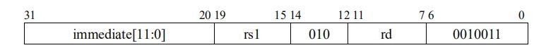
1.2. SLTI
Set if Less Than Immediate
The SLTI instruction format :
SLTI rd,rs1,immediate。
x[rd] = x[rs1] <𝑠 sext(immediate)
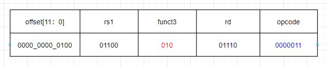
The machine code for SLTI is shown in figure 4, where the OP-IMM field is 001_0011 and funct3 is 010. In SLTI, the “S” stands for set, which means to set the value of rd to 0 or 1 after signed comparison of rs1 and the sign-extended immediate value. Note that the instruction sets the bit to 1 if the condition is true and 0 if it is false. The condition tested by this instruction is LT (less than), which means it checks if the value in rs1 is less than the immediate value. SLTI stands for set if less than immediate.
SLTI x13,x12,5
Compare the value in register x12 with the immediate value 5 (sign-extended to 5), and if the value in x12 is less than 5 (signed comparison), set x13 to 1.
1.3. SLTIU
Set if Less Than Immediate Unsigned
instruction format :
SLTIU rd,rs1,immediate . x[rd]= x[rs1] <𝑢 sext(immediate)
Its machine code is shown in Figure 5, with OP-IMM of 001_0011 and funct3 of 011 for the SLTIU instruction. The only difference between SLTIU and SLTI is that “U” stands for unsigned number, and the immediate value is sign-extended and treated as an unsigned number for comparison, with the result being written back to the register.
If we compare two 8-bit binary numbers, -1: 8’b1111_1111, and -2: 8’b1111_1110, when compared as signed numbers, -2 is less than -1. If compared as unsigned numbers, the comparison still holds. However, if we compare -2 and +1: 8’b0000_0001 as unsigned numbers, then 1111_1110 > 0000_0001, and 254 is greater than 1.
1.3.1 Example
SLTIU x13,x12,-1
To compare register x12 with immediate value -1 (sign-extended to 0xffffffff), and set x13 to 1 if the value in register x12 is less than 0xffffffff when treated as an unsigned number.
1.3.2 The Pseudo-Instruction SEQZ
The pseudo-instruction SEQZ (set if equal to zero) can be expressed as SEQZ rd, rs1, which is equivalent to the instruction SLTIU rd, rs1, 1. This pseudo-instruction is a special case of SLTIU and is commonly used. In unsigned numbers, there is only one case where rs1 is less than “1”, which is when rs1 equals 0.
Therefore, if the comparison SLTIU rd, rs1, 1 holds, it can also be considered that SEQZ rd, rs1 holds when rs1 equals 0.
1.4. ANDI
And Immediate
instruction format :
ANDI rd,rs1,immediate。x[rd] = x[rs1] & sext(immediate)

The machine code for the ANDI instruction is shown in Figure 6, with OP-IMM of 001_0011 and funct3 of 111. The ANDI instruction performs a bitwise AND operation between the sign-extended immediate value and the value in register rs1. The result is written back to the destination register rd.
1.4.1 Example
ANDI x13,x12,5
To perform a bitwise AND operation between the value in register x12 and the sign-extended immediate value 5, and store the result in register x13
1.5. ORI
OR Immedicate
instruction format :
ORI rd,rs1,immediate。x[rd] = x[rs1] | sext(immediate)

1.5.1 Example
ORI x13,x12,5
To perform a bitwise OR operation between the value in register x12 and the sign-extended immediate value 5, and store the result in register x13
1.6. XORI
XOR Immediate
instruction format :
XORI rd,rs1,immediate。x[rd] = x[rs1] ^ sext(immediate)

The machine code for the XORI instruction is shown in Figure 8, with OP-IMM of 001_0011 and funct3 of 100. The XORI instruction performs a bitwise XOR operation between the sign-extended immediate value and the value in register rs1. The result is written back to the destination register rd.
1.6.1 Pseudo-instruction NOT
Pseudo-instruction NOT: NOT rd, rs1 (equivalent to XORI rd, rs1, 12’hfff).
The NOT instruction performs a bitwise negation operation on the value in register rs1 and stores the result in register rd. This is achieved by XORing the sign-extended value of 12’hfff with the value in rs1. Since XORing 1 with any value performs a bitwise negation, XORing 12’hfff with rs1 achieves the same result.
1.6.2 example
XORI x13,x12,5
XOR the number in register x12 with the signed immediate number 5 after sign extension, and write the result to register x13.
RISC-V instructions are flexible. The machine code formats of the instructions above do not enforce a specific register for rs1 and rd. Users can choose the corresponding registers from the 32 general-purpose registers as needed when writing assembly programs, and rs1 and rd can even be the same register.
2. I-Type Shift Instructions
This article will continue to introduce the remaining integer register-immediate instructions in the I-type (here it is the shift instruction).
Figure 1 shows a shift instruction with an immediate value for the number of shifts. Other shift instructions will be introduced later. From the machine code format, it can be seen that these three instructions are somewhat different from the six I-type instructions mentioned earlier in the text. The I-immediate in this article is divided into two parts.
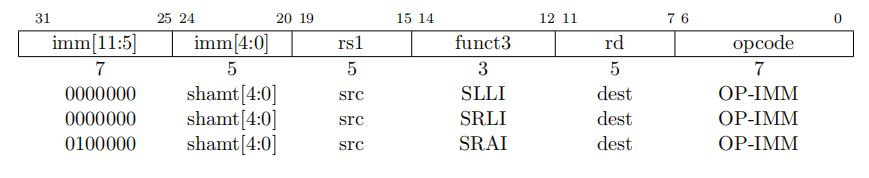
shamt – shift amount
The imm[10] (bit 30 of the machine code) in imm[11:5] is used to differentiate between the types of shifts. The SLLI and SRLI instructions have a value of 0 for bit 30, while the SRAI instruction has a value of 1 for bit 30 of the machine code.
2.1. SLLI
Shift Left Logical Immediate
Instruction Format:
SLLI rd,rs1,shamt x[rd] = x[rs1] ≪ shamt

The machine code is shown in Figure 2.2, with OP-IMM for SLLI being 001_0011, funct3 being 001, and IMM[10] being 0.
The number of bits to shift is determined by imm[4:0]. This instruction left-shifts the value in rs1 by shamt[4:0] bits, with zeroes filled in for the lower bits of rs1, and the result is written to rd.
2.1.1 Example
SLLI x13,x12,3
Left shift the value in register x12 by 3 bits and write the result to register x13.
- OP-IMM: 001_0011
- funct3: 001
- shamt: 5’b0_0011
- bit 25-31: 7’b000_0000
- rs1: 5’b0_1100
- rd: 5’b0_1101
SLLI x13,x12,3machine code:
0000000_00011_01100_001_01101_0010011 .
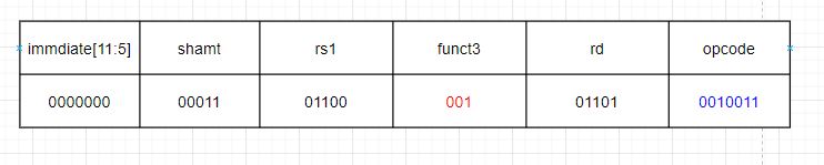
The corresponding hexadecimal representation is 0x0036_1693 in 32-bit format.
2.2. SRLI
Shift Right Logical Immediate
Instruction Format:
SRLI rd,rs1,shamt。x[rd] = x[rs1] ≫𝑢 shamt
The machine code for the SRLI instruction with OP-IMM = 0010011, funct3 = 101, rd, rs1, and shamt[4:0] specified according to the given parameters is shown in Figure 2.3.
The SRLI instruction performs a logical right shift on the value in register rs1 by shamt[4:0] bits, filling the vacated bits with zeroes, and stores the result in register rd.

2.2.1 Example
SRLI x13,x12,5
Perform a logical right shift on the value in register x12 by 5 bits, fill the vacated bits with zeroes, and store the result in register x13

The OP-IMM and funct3 fields of the SRLI and SRAI instructions have the same encoding.
2.3 SRAI
Shift Right Arithmetic Immediate
Instruction Format:
SRAI rd,rs1,shamt。x[rd] = x[rs1] ≫𝑠 shamt

The SRAI instruction’s machine code is shown in Figure 2.4. It has an OP-IMM field of 001_0011, a funct3 field of 101, and an IMM[10] value of 1. The instruction performs an arithmetic right shift on the value in register rs1 by shamt[4:0] bits, filling the vacated bits with the value of rs1[31] (the sign bit), and stores the result in register rd.
2.3.1 Example
SRAI x13,x12,3
Perform an arithmetic right shift of 3 bits on the value in register x12 and store the result in register x13.
2.3.2 Please Note:
The difference between the two instructions is determined by the value of imm[10]:
- If imm[10] is 0, the instruction is SRLI (Shift Right Logical Immediate), which performs a logical right shift and fills the vacated bits with zeroes.
- If imm[10] is 1, the instruction is SRAI (Shift Right Arithmetic Immediate), which performs an arithmetic right shift and fills the vacated bits with the sign bit (the leftmost bit).
Both instructions shift the value in the specified register by the immediate value specified in shamt[4:0] and write the result to the specified destination register.
2.4 Example to Distinguish Between Arithmetic Right Shift and Logical Right Shift
Distinguish between arithmetic right shift and logical right shift, for example, for the binary number 1100_1100 (explained here using 8-bit numbers, but in RV32I the numbers stored in registers are 32-bit).
Shifting the binary number 1100_1100 by 3 bits to the right using arithmetic right shift gives the result 1111_1001.
Similarly, shifting the binary number 0011_0011 by 3 bits to the right using arithmetic right shift gives the result 0000_0110.
On the other hand, shifting 1100_1100 by 3 bits to the right using logical right shift gives the result 0001_1001.
Similarly, shifting 0011_0011 by 3 bits to the right using logical right shift gives the result 0000_0110.
3. U-Type Integer Register-Immediate Instructions
The two U-type instructions introduced here operate on the program counter (PC) rather than the general-purpose registers (x0-x31), and are represented by the AUIPC opcode.
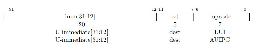
Figure 1 shows the machine code formats of LUI and AUIPC, and comparing them with the machine code of the I-type instructions, it can be seen that the U-type instructions do not have rs1 and funct3 fields, but instead have a 20-bit immediate value (including the 12-bit immediate value in the I-type instructions).
Note that the opcode of U-type instructions is different from that of I-type instructions. Like the I-type instructions, the immediate value in U-type instructions is fixed at 20 bits and is named U-immediate[31:12], as shown in Figure 3.1.
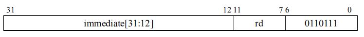
3.1 LUI
Load Upper Immediate
Instruction Format:
LUI rd,immediate。x[rd] = sext(immediate[31:12] << 12)
The machine code for LUI is shown in Figure 3.2, with opcode 011_0111. This instruction writes the U-immediate value to the top 20 bits of the rd register, with the lower 12 bits of rd set to zero.
3.1.1 Example
LUI x8,0xf0000
To load 0xf000_0000 into the x8 register:
- opcode [o-6]: 011_0111
- rd [7-11]: 5’b01000
- immediate[31:12] :1111_0000_0000_0000_0000
- 32 bit machine code: 1111_0000_0000_0000_0000_01000_0110111 ( 32’hF000_0437)
Notice:
- 32′ – 32 bit
- b01000 b – binary
- hF000_0437 h – Hex
3.2 AUIPC
Add Upper Immediate to PC
Instruction Format:
AUIPC rd,immediate。x[rd] = pc + sext(immediate[31:12] << 12)
The machine code for AUIPC is shown in Figure 3.3, with opcode 001_0111. This instruction sign-extends the 20-bit immediate value, left-shifts it by 12 bits, adds it to the current PC value, and writes the result to the rd register.

3.2.1 Example
AUIPC x12,0xf00
To add 0xf0_0000 to the current PC and load the result into the x12 register
Notice:
Most immediates are either very small or require all XLEN bits. RISC-V has chosen asymmetric immediate encoding (12 bits for regular instructions, plus 20 bits for special “upward” instructions like LUI) to increase the opcode space available for regular instructions.
The combination of the 12-bit immediate in AUIPC and JALR (which we will cover in a subsequent article) can be used to transfer control to any 32-bit PC-relative address, while AUIPC added to the 12-bit immediate offset in a regular load or store instruction can access any 32-bit PC-relative data address.
The current PC can be obtained by setting the U-immediate of AUIPC to 0.
WER
4. R-Type Integer Register-Register Instructions
The register-register instruction format can directly operate on the data in registers without involving memory read or write operations, making it faster. R-Type instructions are a common register-register instruction format, widely used for arithmetic, logical, and comparison operations, among others.
The R-Type instructions are instructions with a “register-register” format, where the operands and results are stored in registers.
R-Type instructions are typically used to perform arithmetic or logical operations.
RV32I defines ten arithmetic R-Type operations. All of these operations read source operands from registers rs1 and rs2, and write the result into register rd. It should be noted that R-Type instructions do not have immediate values and can only use registers rs1, rs2, and rd.
The funct7 and funct3 fields select the operation type, as shown in Figure 4.1.
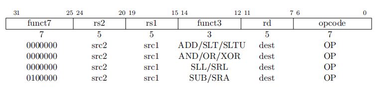
There are a total of 10 instructions in R-Type, with the opcode named OP and a value of 011_0011 (all R-Type instructions share the same opcode value).
4.1 ADD
The “ADD” instruction is an example of a RISC-V “R-type” instruction, where R stands for “register”. R-type instructions operate on two source registers and store the result in a destination register.
We have learned the operation principle of the ADDI instruction in the I-Type integer register-immediate instruction, which is similar to the ADD instruction but with the immediate value split into a funct7 field of 7 bits and an rs2 field of 5 bits.
The ADD instruction format
ADD rd, rs1, rs2, where x[rd] = x[rs1] + x[rs2].
The funct7 field is 000_0000 and the funct3 field is 000. This instruction adds the values in registers rs1 and rs2 and writes the result to rd.

Note that this is not the addition of bit 15-19 and bit 20-24 of the machine code, but the addition of the values in the registers corresponding to their index numbers.
Similar to ADDI, any overflow is ignored, and only the lower XLEN bits are written to rd.
An example of overflow in addition is given, where adding two 8-bit signed binary numbers 0100_0000 (64) and 0111_0000 (112) results in 1011_0000 (-80), which is obviously incorrect.
4.1.1 Example
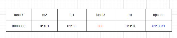
ADD x14,x12,x13
Add the numbers in registers x12 and x13 and store the result in register x14.
- OP-IMM: 011_0011
- funct3: 000
- funct7: 7’b000_0000
- rs2: 5’b0_1101
- rs1: 5’b0_1100
- rd: 5’b0_1110
ADD x14,x12,x13
machines code is: 0000000_01101_01100_000_01110_0110011 (32’ h00d6_0733)
4.2 SLT
Set Less Than
It compares two signed source integers, and sets the destination register to 1 if the first integer is less than the second integer, or 0 otherwise.
Format Instruction:
SLT rd,rs1,rs2. x[rd] = x[rs1] <𝑠 x[rs2]

4.2.1 Example
SLT x14,x12,x13
Compare the numbers in registers x12 and x13 as signed integers. If the number in x12 is less than the number in x13, set the number in x14 register to 1, otherwise set it to 0.
The SLT instruction does not perform an actual subtraction operation between the two integers. Instead, it performs a comparison of the sign bits and magnitude of the integers to determine the result.
If either rs1 or rs2 contains an unsigned value, then the comparison is performed as if the unsigned value were signed. This can lead to unexpected results if the unsigned value has the sign bit set.
SLT can be useful in programming situations where we need to compare two signed integers and make a decision based on the result of the comparison.
4.3 SLTU
Set Less Than Unsigned
Instruction Format:
SLTU rd,rs1,rs2. x[rd] = x[rs1] <𝑢 x[rs2]

Compare the numbers in the x12 and x13 registers as unsigned numbers. If the number in the x12 register is less than the number in the x13 register, set the x14 register to 1, otherwise set it to 0.
4.4 AND
AND (&)
Instruction Format:
AND rd,rs1,rs2. x[rd] = x[rs1] & x[rs2]

As shown in Figure 4.5, the funct7 of the AND instruction is 000_0000, and the funct3 is 111. This instruction writes the result of rs1 & rs2 into rd, where “&” means bitwise AND between rs1 and rs2.
4.4.1 Example
AND x14,x12,x13
Write the result of bitwise AND between the numbers in the x12 and x13 registers into the x14 register.
4.5. OR
OR ( | )
Instruction Format:
OR rd,rs1,rs2. x[rd] = x[rs1] | x[rs2]

As shown in Figure 4.6, the funct7 of the OR instruction is 000_0000, and the funct3 is 110. This instruction writes the result of rs1 | rs2 into rd, where “|” means bitwise OR between rs1 and rs2.
4.5.1 Example
OR x14,x12,x13
Write the result of bitwise OR between the numbers in the x12 and x13 registers into the x14 register.
4.6. XOR
XOR ( ^ )
Instruction Format:
XOR rd,rs1,rs2. x[rd] = x[rs1] ^ x[rs2]
As shown in Figure 4.7, the funct7 of the XOR instruction is 000_0000, and the funct3 is 100. This instruction writes the result of rs1 XOR rs2 into rd, where “XOR” means bitwise exclusive OR between rs1 and rs2.

4.6.1 Example
XOR x14,x12,x13
Write the result of bitwise XOR between the numbers in the x12 and x13 registers into the x14 register.
4.7. SLL
Shift Left Logical
Instruction Format:
SLL rd,rs1,rs2. x[rd] = x[rs1] ≪ x[rs2]
As shown in Figure 4.8, the funct7 of the SLL instruction is 000_0000, and the funct3 is 001. This instruction left shifts rs1 by the number of bits specified by rs2 (the value in this register), filling the vacated positions with 0, and writes the result into the rd register. The lower 5 bits of the rs2 register represent the number of bits to be shifted (up to a maximum of 2^5 – 1 = 31), and its higher bits are ignored.

4.7.1 Example
SLL x14,x12,x13
Left shift the value in x12 by the number of bits specified by the lower 5 bits (higher bits are ignored) of the number stored in the x13 register, filling the vacated positions with 0, and write the result into the x14 register.
4.8. SRL
Shift Right Logical
Instruction Format:
SRL rd,rs1,rs2. x[rd] = x[rs1] ≫𝑢 x[rs2]

As shown in Figure 4.9, the funct7 of the SRL instruction is 000_0000, and the funct3 is 101. This instruction right shifts rs1 by the number of bits specified by rs2 (the value in this register), filling the vacated positions with 0, and writes the result into the rd register. The lower 5 bits of the rs2 register represent the number of bits to be shifted (up to a maximum of 2^5 – 1 = 31), and its higher bits are ignored.
4.8.1 Example
SRL x14,x12,x13
Right shift the value in x12 by the number of bits specified by the lower 5 bits (higher bits are ignored) of the number stored in the x13 register, filling the vacated positions with 0, and write the result into the x14 register.
4.9. SRA
Shift Right Arithmetic
Instruction Format:
SRA rd,rs1,rs2

As shown in Figure 4.10, the funct7 of the SRA instruction is 010_0000, and the funct3 is 101. This instruction right shifts rs1 by the number of bits specified by rs2 (the value in this register), filling the vacated positions with the value of the most significant bit (rs1[31]) of the rs1 register, and writes the result into the rd register. The lower 5 bits of the rs2 register represent the number of bits to be shifted (up to a maximum of 2^5 – 1 = 31), and its higher bits are ignored.
4.9.1 Example
SRA x14,x12,x13
Shift the value in x12 register to the right by the number of bits specified by the lower 5 bits of the x13 register (ignoring the higher bits), fill the vacated positions with the value of the most significant bit (sign bit) of the value stored in x12 register, and write the result into the x14 register.
Note:
In the three shift instructions mentioned above, the value in the rs1 register is only copied, and the original value remains unchanged.
4.10 SUB
SUBtract
Instruction Format:
SUB rd,rs1,rs2. x[rd] = x[rs1] − x[rs2]
The SUB instruction shown in Figure 11 has a funct7 of 010_0000 and funct3 of 000. This instruction subtracts the value in the rs2 register from the value in the rs1 register, ignoring arithmetic overflow.

4.10.1 Example
SUB x14,x12,x13
Subtract the value stored in register x13 from the value stored in register x12, and write the result to register x14 (ignoring arithmetic overflow).
5.Conditional and Unconditional Jump Instructions
5.1 Control Transfer Instruction
In RV32I, control transfer instructions are mainly divided into two categories: unconditional jump and conditional jump.
5.2 Unconditional Jump Instructions
Unconditional jump instructions all use PC-relative addressing. The unconditional jump mainly includes two instructions: JAL and JALR.
5.2.1 JAL
Jump And Link
The JAL instruction uses the J-type format (JAL is the only J-type instruction in RV32I).
Instruction Format
JAL rd,offset x[rd] = pc+4; pc += sext(offset)
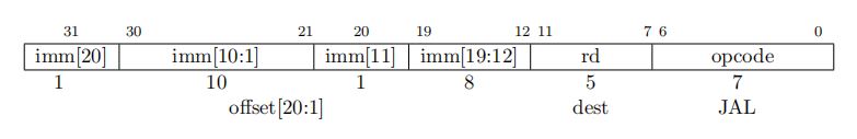
Its machine code format is shown in Figure 5.1 Its opcode is 110_1111. The instruction stores the address of the next instruction (PC + 4) in the rd register, and then sets the PC to the current value plus the sign-extended offset.
Note that the offset is sign-extended. As can be seen, the offset is aligned with 2 bytes (offset [20:1]), although all instruction addresses in RV32I are aligned with 4 bytes, JAL may also be used for compatibility with the C extension instruction set. Therefore, it defaults that bit 0 of the offset is 0 (that is, aligned with 2 bytes).
Therefore, the address range of JAL jump is +/- 1MB. (2^21 = 2MB = +/- 1MB)
The standard software calling convention uses x1 register as the return address register (rd), and x5 can be used as a backup link register. Because the offset in the JAL instruction is the offset relative to the PC, precise address differences are required when writing, and if any assembly instructions are added or deleted, the offset in JAL may need to be modified again, which imposes a great burden on the use of the JAL instruction. Therefore, when using the JAL instruction, it is generally better to use JAL rd, label instead of JAL rd, offset.
The label in JAL rd, label is a tag used to mark the position of a certain segment of the program, which provides a jump entry for jump and branch statements in the program (examples of using labels can be found here). The compiler will automatically calculate the label and the offset from the current instruction.
5.2.1.1 Example
JAL x1,main
To jump to the main function and store the address of the next instruction in the x1 register
The pseudo-instruction “JAL main” corresponds to the actual instruction “JAL x1, main”.
The pseudo-instruction “J main” corresponds to the actual instruction “JAL x0, main”.
Notice:
- There are two reasons why x5 register is chosen as a backup link register:
-
- It is used as a temporary variable in the standard calling convention.
- It differs from the regular link register x1 by only 1 bit, as x1 is
0_0001and x5 is0_0101.
- If the rd operand is omitted in the JAL instruction, then the default value for rd is x1.
- The pseudo-instruction “J label”, the corresponding actual instruction is “JAL x0, label”. So the rd operand is set to x0 in this case
5.2.2 JALR
Jump And Link Redirect
The JALR instruction uses the I-type encoding format in RISC-V architecture.
Instruction Format
JALR rd,offset(rs1)
t = pc + 4; pc = (x[rs1]+sext(offset)) & ~1;
x[rd]=t
Equivalent to
t = pc + 4; pc = (x[rs1]+sext(offset)) & 0xffff_fffe; x[rd]=t // RV32I
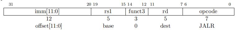
Machine code as above Figure 5.2.
- opcode: 110_0111
- funct3: 000
The instruction sets the PC to the value in the rs1 register plus the sign-extended offset, sets the least significant bit of the calculated address to 0, and writes the original value of PC + 4 to the rd register. If the destination register is not needed, rd can be set to x0.
The offset of JALR is also sign-extended, and the address range of the offset in JALR is +/-2KB (2^12 = 4096 = 4KB = +/-2KB) relative to the address stored in the rs1 register. The JALR instruction is designed to allow two instruction sequences to jump to any position within the 32-bit absolute address range (because the jump range of the JAL instruction is not large enough).
5.2.2.1 Example
JALR x13,0(x1)
The instruction jumps to the address stored in register x1 and stores the address of the next instruction (PC+4) in register x13.
Other examples of pseudo instructions:
JR x1 => JALR x0, x1, 0
RET => JALR x0, x1, 0
JALR x13 => JALR x1, x13, 0
Generally, LUI and JALR can be used together to jump to a 32-bit absolute address range, while AUIPC and JALR can be used together to jump to a 32-bit address range relative to PC.
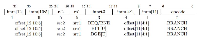
5.3. Conditional Branch Jump
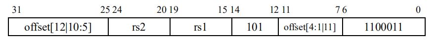
All branch instructions are encoded in B-type format, and their machine code is shown in Figure 5.3 The 12-bit immediate value is encoded as a signed offset (offset[12:1]) in multiples of 2 bytes.
Although all instruction addresses in RV32I are aligned to 4-byte boundaries, JAL may still be used for compatibility with the C extension instruction set, so offset bit 0 is assumed to be 0 (i.e., 2-byte alignment) by default.
The target address is composed of the address of the branch instruction plus the sign-extended offset, with a range of : 213 = 8192 = 8 KB = +/- 4 KB
Similar to JAL, the branch instruction can also use labels instead of offsets, for example BEQ rs1, rs2, label.
5.3.1 BEQ
Branch If EQual
Instruction Format:
BEQ rs1,rs2,offset. if (rs1 == rs2) pc += sext(offset)
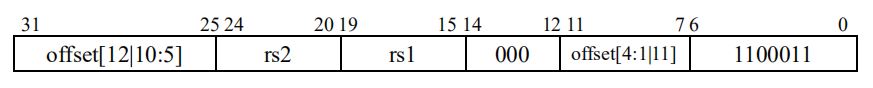
As Shown in Figure 5.4,
- opcode: 110_0011
- funct3: 000
This instruction compares the values in the rs1 and rs2 registers. If they are equal, it sets the value of the PC to the current value plus the sign-extended offset.
5.3.1.1 Example
BEQ x12,x13,LOOP
Compare the values in registers x12 and x13. If they are equal, jump to the label LOOP.
5.3.2 BNE
Branch if Not Equal
Instruction Format:
BNE rs1,rs2,offset. if (rs1 ≠ rs2) pc += sext(offset)

As Shown in Figure 5.5,
- opcode: 110_0011
- funct3: 001
This instruction compares the values in the rs1 and rs2 registers. If they are not equal, it sets the value of the PC to the current value plus the sign-extended offset.
5.3.2.1 Example
BNE x12,x13,LOOP
Compare the values in registers x12 and x13. If they are not equal, jump to the label LOOP.
5.3.3 BLT
Branch if Less Than
Instruction Format:
BLT rs1,rs2,offset. if (rs1 <s rs2) pc += sext(offset)
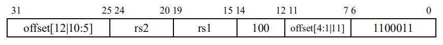
As Shown in Figure 5.6,
- opcode: 110_0011
- funct3: 100
This instruction compares the value in the rs1 register with the value in the rs2 register (both considered as signed numbers). If the value in rs1 is less than the value in rs2, it sets the value of the PC to the current value plus the sign-extended offset.
5.3.3.1 Example
BLT x12,x13,LOOP
Compare the signed values in registers x12 and x13. If the value in register x12 is less than that in register x13, jump to the label LOOP.
5.3.4 BLTU
Branch if Less Than,Unsigned
Instruction Format:
BLTU rs1,rs2,offset. if (rs1 <u rs2) pc += sext(offset)

As Shown in Figure 5.7,
- opcode: 110_0011
- funct3: 110
This instruction compares the value in the rs1 register with the value in the rs2 register (both considered as unsigned numbers). If the value in rs1 is less than the value in rs2, it sets the value of the PC to the current value plus the sign-extended offset.
5.3.4.1 Example
BLTU x12,x13,LOOP
Compare the values in registers x12 and x13 as unsigned numbers, and if the value in register x12 is less than the value in register x13, jump to the label LOOP.
5.3.5 BGE
Branch if Greater than or Equal
Instruction Format:
BGE rs1,rs2,offset. if (rs1 ≥s rs2) pc += sext(offset)
As Shown in Figure 5.8,
- opcode: 110_0011
- funct3: 101
The instruction compares the value in register rs1 with the value in register rs2 (both treated as signed numbers), and if rs1 is greater than or equal to rs2, it sets the PC to the current value plus a sign-extended offset.
5.3.5.1 Example
BGE x12,x13,LOOP
Compare the values in registers x12 and x13 as signed integers. If the value in x12 is greater than or equal to the value in x13, jump to the label LOOP.
5.3.6 BGEU
Branch if Greater than or Equal,Unsigned
Instruction Format:
BGEU rs1,rs2,offset. if (rs1 ≥u rs2) pc += sext(offset)

As Shown in Figure 5.9,
- opcode: 110_0011
- funct3: 111
The instruction is to compare the value in register rs1 with the value in register rs2 as unsigned integers. If rs1 is greater than or equal to rs2, then the PC value is set to the current value plus the sign-extended offset.
5.3.6.1 Example
BGEU x12,x13,LOOP
Unsigned compare the values in register x12 and x13, if the value in x12 is greater than or equal to the value in x13, jump to label LOOP.
6.Load/Store Instructions
6.1. Load Store Instructions
RV32I is a load-store architecture. Only load and store instructions can access memory and peripherals (registers inside the CPU can only be operated by arithmetic instructions).
Load and store instructions exchange values between registers and memory/peripherals.
The load instruction is encoded as I-type with an opcode of 0000 011, while the store instruction is encoded as S-type with an opcode of 0100 011, as shown in Figure 6.1.
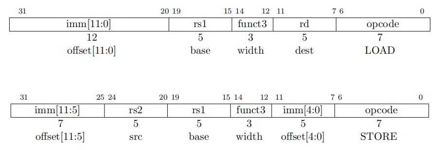
The effective address is obtained by adding the sign-extended 12-bit immediate value (in the case of the store instruction, the immediate value is split into two parts) to the value in the rs1 register.
Generally, the load instruction copies the value at the effective address in memory/peripherals to the rd register, while the store instruction copies the value in the rs2 register to the effective address in memory/peripherals.
6.2. LOAD
6.2.1.LW
Load Word
Instruction Format:
LW rd,offset(rs1). x[rd] = sext ( M [x[rs1] + sext(offset) ] [31:0] )

As Shown in Figure 6.2.
- opcode:000 0011
- funct3: 010
This instruction reads four bytes (one word) from the effective address and writes it into the rd register.
6.2.1.1 Example
LW x13,4(x12)
Read four bytes from the memory address corresponding to the value in register x12 plus a 4-byte offset, and store the result in register x13.
- opcode: 000_0011
- funct3: 010
- immediate: 12’b0000_0000_0100
- rs1: 5’b0_1100
- rd: 5’b0_1101
the machine code for LW x13, 4(x12) is 0000 0000 0100 0110 0010 0110 1000 0011Hex: 32’h0046_2683
6.2.2.LH
Load Halfword
Instruction Format:
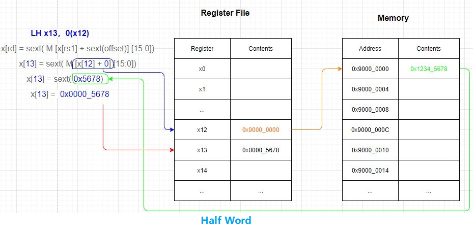
LH rd,offset(rs1). x[rd] = sext( M [x[rs1] + sext(offset)] [15:0])

As Shown in Figure 6.3.
- opcode:000 0011
- funct3: 001
This instruction reads two bytes (halfword) from the effective address, sign-extends it, and writes the result into the rd register.
6.2.2.1 Example
LH x13,0(x12)
Read two bytes from the memory address corresponding to the value in register x12, sign-extend it, and store the result in register x13, as shown in the following figure
6.2.3.LHU
Load Halfword,Unsigned
Instruction Format:
LHU rd,offset(rs1). x[rd] = M[x[rs1] + sext(offset)][15:0]

As Shown in Figure 6.5.
- opcode:000 0011
- funct3: 101
This instruction reads two bytes (halfword) from the effective address, zero-extends it, and writes the result into the rd register.
6.2.3.1 Example
LHU x13,0(x12)
Read two bytes from the memory address corresponding to the value in register x12, zero-extend it, and store the result in register x13.
6.2.4.LB
Load Byte
Instruction Format:
LB rd,offset(rs1). x[rd] = sext( M [x[rs1] + sext(offset)] [7:0])

As Shown in Figure 6.6.
- opcode:000 0011
- funct3: 000
This instruction reads a byte from an effective address, sign-extends it, and then writes it into the rd register.
6.2.4.1 Example
LB x13,0(x12)
Read a byte from the corresponding address in the x12 register, sign-extend it, and store it in the x13 register.
6.2.5. LBU
Load Byte,Unsigned
Instruction Format:
LBU rd,offset(rs1). x[rd] = M[x[rs1] + sext(offset)][7:0]

As Shown in Figure 6.7.
- opcode:000 0011
- funct3: 100
This instruction reads a byte from an effective address, zero-extends it, and then writes it into the rd register.
6.2.5.1 Example
LBU x13,0(x12)
Read a byte from the corresponding address in the x12 register, zero-extend it, and store it in the x13 register.
6.3. STORE Instructions
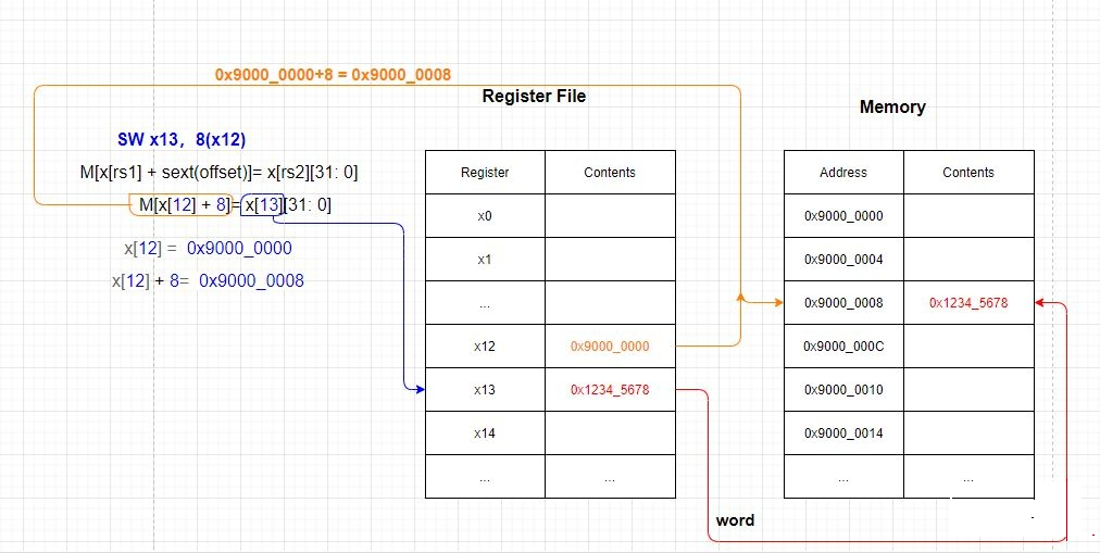
6.3.1 SW
Store Word
Instruction Format:
SW rs2,offset(rs1)。M[x[rs1] + sext(offset)]= x[rs2][31: 0]

As Shown in Figure 6.8.
- opcode:010 0011
- funct3: 010
This instruction stores a word, which is four bytes, from the rs2 register into the effective address.
6.3.1.1 Example
SW x13,8(x12)
Store the four bytes from the x13 register into the effective address computed by adding the value in the x12 register with an offset of 8.
6.3.2 SH
Store Halfword
Instruction Format:
SH rs2,offset(rs1). M[x[rs1] + sext(offset)] = x[rs2][15: 0]

As Shown in Figure 6.10.
- opcode:010 0011
- funct3: 001
This instruction stores a halfword, which is two bytes, from the rs2 register into the effective address.
6.3.2.1 Example
SH x13,0(x12)
Store the low-order two bytes from the x13 register into the corresponding address in the x12 register.
6.3.3 SB
Store Byte
Instruction Format:
SB rs2,offset(rs1). M[x[rs1] + sext(offset)]= x[rs2][7: 0]

As Shown in Figure 6.11.
- opcode:010 0011
- funct3: 000
This instruction stores the low-order byte (i.e., the least significant byte) from the rs2 register into the effective address.
6.3.3.1 Example
SB x13,0(x12)
Store the low-order byte (i.e., the least significant byte) from the x13 register into the corresponding address in the x12 register.
7. RV32I Base Integer Instruction Set
| Format | Name | Pseudocode |
|---|---|---|
|
Load Upper Immediate | rd ← imm |
|
Add Upper Immediate to PC | rd ← pc + offset |
|
Jump and Link | rd ← pc + length(inst) pc ← pc + offset |
|
Jump and Link Register | rd ← pc + length(inst) pc ← (rs1 + offset) ∧ -2 |
|
Branch Equal | if rs1 = rs2 then pc ← pc + offset |
|
Branch Not Equal | if rs1 ≠ rs2 then pc ← pc + offset |
|
Branch Less Than | if rs1 < rs2 then pc ← pc + offset |
|
Branch Greater than Equal | if rs1 ≥ rs2 then pc ← pc + offset |
|
Branch Less Than Unsigned | if rs1 < rs2 then pc ← pc + offset |
|
Branch Greater than Equal Unsigned | if rs1 ≥ rs2 then pc ← pc + offset |
|
Load Byte | rd ← s8[rs1 + offset] |
|
Load Half | rd ← s16[rs1 + offset] |
|
Load Word | rd ← s32[rs1 + offset] |
|
Load Byte Unsigned | rd ← u8[rs1 + offset] |
|
Load Half Unsigned | rd ← u16[rs1 + offset] |
|
Store Byte | u8[rs1 + offset] ← rs2 |
|
Store Half | u16[rs1 + offset] ← rs2 |
|
Store Word | u32[rs1 + offset] ← rs2 |
|
Add Immediate | rd ← rs1 + sx(imm) |
|
Set Less Than Immediate | rd ← sx(rs1) < sx(imm) |
|
Set Less Than Immediate Unsigned | rd ← ux(rs1) < ux(imm) |
|
Xor Immediate | rd ← ux(rs1) ⊕ ux(imm) |
|
Or Immediate | rd ← ux(rs1) ∨ ux(imm) |
|
And Immediate | rd ← ux(rs1) ∧ ux(imm) |
|
Shift Left Logical Immediate | rd ← ux(rs1) « ux(imm) |
|
Shift Right Logical Immediate | rd ← ux(rs1) » ux(imm) |
|
Shift Right Arithmetic Immediate | rd ← sx(rs1) » ux(imm) |
|
Add | rd ← sx(rs1) + sx(rs2) |
|
Subtract | rd ← sx(rs1) – sx(rs2) |
|
Shift Left Logical | rd ← ux(rs1) « rs2 |
|
Set Less Than | rd ← sx(rs1) < sx(rs2) |
|
Set Less Than Unsigned | rd ← ux(rs1) < ux(rs2) |
|
Xor | rd ← ux(rs1) ⊕ ux(rs2) |
|
Shift Right Logical | rd ← ux(rs1) » rs2 |
|
Shift Right Arithmetic | rd ← sx(rs1) » rs2 |
|
Or | rd ← ux(rs1) ∨ ux(rs2) |
|
And | rd ← ux(rs1) ∧ ux(rs2) |
|
Fence | |
|
Fence Instruction |