1.RISC-V Instruction Set Explanation
RISC-V is an open and free instruction set architecture widely used in processors and embedded systems.
The RISC-V instruction set follows the design principles of Reduced Instruction Set Computing (RISC) and is committed to improving the scalability and flexibility of the instruction set.
The RISC-V instruction set consists of 32 general-purpose registers and some special-purpose registers, which programmers can use to store and access data. Among them, general-purpose registers are divided into two types: 32-bit and 64-bit, which are used to store 32-bit and 64-bit data, respectively.
The instructions in the RISC-V instruction set can be divided into the following categories:
- Load/Store instructions: Used to load data from memory into registers or store data from registers into memory.
- Arithmetic/Logic instructions: Used to perform basic arithmetic and logic operations, such as addition, subtraction, multiplication, division, shift, AND, OR, XOR, etc.
- Branch/Jump instructions: Used to implement program control flow, such as conditional branches, unconditional jumps, etc.
- Load/Store atomic instructions: Used to perform atomic operations on data in memory, such as atomic read-modify-write operations.
- Privileged instructions: Used to perform privileged operations, such as entering and exiting privileged mode, reading and writing privileged registers, etc.
- Floating-point instructions: Used to perform floating-point arithmetic, such as addition, subtraction, multiplication, division, modulo, conversion, etc.
- Vector instructions: Used to perform vector operations, such as vector addition, vector multiplication, vector dot product, etc.
- Atomic instructions: Used to implement multi-threaded and concurrent operations, such as atomic read-modify-write operations.
The above are the common instruction types in the RISC-V instruction set, with common instructions such as ADD, SUB, AND, OR, XOR, SLT, etc. These instructions can be written in assembly language and ultimately translated into binary code for execution.
2. RISC-V General Purpose Registers and Program Counter
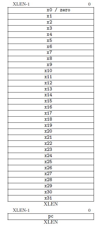
The CPU contains 32 general-purpose registers, sometimes referred to as the general-purpose register file, as shown in Figure 1.
The general-purpose registers are named X0-X31. The value of the first register X0 is hardwired to 0, so its value is always 0. The other registers X1-X31 are both readable and writable. 0-31 is also called the index number, which can be understood as the address of the register.
When an instruction needs to call a general-purpose register, it can be looked up through the index number. For a 32-bit system, the width of all general-purpose registers is 32 bits, and the total number of registers is also 32.
PC (program counter) is a program counter and also a register. In the CPU, the PC register is not included in the above 32 general-purpose registers, and the register file does not include PC. The width of PC is the same as that of general-purpose registers. The value of XLEN is generally related to the RISC-V CPU architecture.
If it is a 32-bit architecture CPU, then the value of XLEN is 32.
In Figure 1, XLEN-1 = 32-1 = 31, which means the highest bit in a general-purpose register is 31.
In a 64-bit CPU, the width of general-purpose registers is 64, and the width of PC is also 64 bits, and the highest bit is 64-1 = 63.
3. RISC-V Assembly Instruction Types
RV32I can be divided into six basic instruction formats:
- R-type instructions for register-to-register operations
- I-type instructions for immediate and load operations
- S-type instructions for store operations
- B-type instructions for conditional jump operations
- U-type instructions for long immediate values
- J-type instructions for unconditional jump operations.
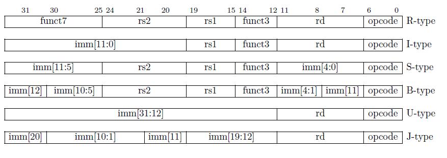
Figure 2 shows the machine code format for the six basic instruction types.

3.1 R-Type
R-type instructions are operations without immediate values (imm, also called immediate) that can be obtained immediately without having to retrieve from registers. The binary format of the R-type assembly instruction machine code is shown in Figure 2.
The length of a binary instruction is 32 bits. Bits 0-6 (7 bits) are the opcode (operation code), which is used to identify the type of instruction.
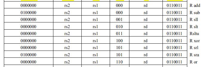
Figure 3 shows the opcode of some R-type assembly instructions. It can be seen that all opcode of R-type instructions are the same, which is 011_0011. However, funct3 and funct7 (in Fig 2) in bits 12-14 and bits 25-31 are different, and they are used to distinguish different R-type assembly instructions.
That is, the opcode determines the rough classification of the instruction, and funct3 and funct7 determine the more detailed classification of the instruction. The index number of rd (destination register) is in bits 7-11 of R-type instruction.
The rd register is used to store the result. Rs1 (source register 1) and rs2 (source register 2) are called source registers, and in most cases, instructions need to read the values of these two source registers for subsequent operations. The index number of rs1 is in bits 15-19, and the index number of rs2 is in bits 20-24.
When the value of the rd index number in the instruction is 5’b00011, which is decimal 3, the CPU will find the X3 register as the rd register among the 32 general-purpose registers, according to the value in bit 7-11, and finally write the result to the x3 register.
If the values in bit 15-19 and bit 20-24 in the rs1 and rs2 index number positions of the binary assembly instruction are 2 and 4, respectively, the CPU will detect that the corresponding general-purpose registers for rs1 and rs2 in the instruction are x2 and x4, and will read values from registers x2 and x4 for the subsequent operation.
Note:
The format of RISC-V assembly instructions is very clear. In the actual coding process, the arrangement of encoding positions is meaningful. For example, the encoding positions of the three register index numbers in different instruction formats are always fixed: rd is in bit 7-11, rs1 is in bit 15-19, and rs2 is in bit 20-24.
Even if some registers are not used in some instructions, such as rs2 in the second instruction type I-type, the index numbers of rs1 and rd are still in their corresponding positions. For example, funct3 is in bit 12-14 in S-type, which is consistent with its position in R-type. Opcode is in all instruction formats, and its position never changes, always in bit 0-6.
3.2. I-Type
Based on the machine code format of R-type assembly instructions, the only difference in I-type is that bits 20-31 (the high 12 bits) represent an immediate value. The other parts are very similar to R-type. Of course, the opcode of I-type must be different from the opcode values of other types of assembly instructions, because they correspond to different operations.
3.3. S-Type
The characteristic of S-type instructions is that they do not have an rd register. In this type of instruction, the immediate (imm) is divided into two parts: imm[11:5] is in bit 25-31, and imm[4:0] is in bit 7-11. The 5 bits of imm[4:0] occupy the position of rd, indicating that this instruction format does not require write-back. imm[11:5] occupies the position of funct7.
3.4. U-Type
The U-type instruction provides a 20-bit immediate (imm[31:12], which is shifted left by 12 bits). The final result of the operation is related to the 20-bit immediate value, and the result is written back to the rd register. The opcode determines the type of operation. The U-type instruction does not have funct3, rs1, rs2, and funct7. The structure of this type of instruction is very simple.
3.5. B-Type
The B-type instruction is mainly used as a jump instruction, and it is a conditional jump, that is, the jump is determined by judging whether the condition is met. It can be compared to an if statement in Verilog language. The machine code structure of B-type can be seen in Figure 2, and the instruction does not include rd registers and funct7, but includes rs1, rs2, funct3, and immediate values.
The immediate value of the B-type instruction is divided into two areas, imm[12|10:5] and imm[4:1|11]. The encoding of the immediate of the B-type instruction is scrambled, which is not detailed here, mainly to increase the shared parts with other formats. However, since the encoding is scrambled, the corresponding decoding order needs to be adjusted during CPU execution, and the CPU needs to restore the scrambled immediate number in order.
3.6. J-Type
The J-type instruction format is very similar to the U-type, with only Rd register, immediate, and opcode. The immediate in J-type instructions is also shuffled. This means that during decoding, the CPU needs to first concatenate the immediate number in the correct order to restore the original immediate number.
Note:
The immediate field in B-type instructions is based on the S-type instruction format with a one-bit rotation, and similarly, the immediate field in J-type instructions is based on the U-type instruction format with a 12-bit rotation. Therefore, RISC-V actually has only four basic instruction formats, but it is conservatively regarded as having six formats. Since the immediate fields in B-type and J-type instructions do not include bit 0, their immediate value are always multiples of 2.
Instructions with all bits set to 0 or 1 are considered illegal RV32I instructions, but they are often used for debugging or catching common errors.
3.7 What is imm in RISC-V Instruction Set ?
In RISC-V instruction set architecture, “imm” stands for “immediate”. An immediate value is a constant value that is encoded directly in the instruction itself, rather than being loaded from memory or a register.
The immediate value can be signed or unsigned, and its size can vary depending on the instruction. For example, the “addi” instruction adds an immediate value to a register, and the “lui” instruction loads an immediate value into the upper 20 bits of a register.
In RISC-V, immediate values can be represented in different formats, such as 5-bit, 12-bit, or 20-bit. The immediate value is sign-extended to the full register width before it is used in the instruction, which means that the sign bit is replicated to fill the upper bits of the register.