1.Logic Variables
Variables in Boolean algebra are called logic variables, typically represented by uppercase letters such as A, B, C, D, etc. Logic variables can only take two values, 0 and 1, which are known as logic constants. They do not represent the magnitude of a quantity, but rather two opposing logic states, such as true/false, on/off, high/low, open/closed, etc. Logic variables can be divided into input variables and output variables, and relationships can be established between inputs and outputs. This is the most basic means of using mathematics to solve real-world problems.
2.Types of Logic Operations
In Boolean algebra, there are only two logic values, 0 and 1, and three basic logic operations: AND, OR, and NOT. There are also several derived logic operations, including NAND, NOR, XOR, and XNOR. Basic logic operations AND, OR, and NOT have been introduced in binary logic operations, and the following lessons will explain and apply these operations in more detail from an algebraic perspective.
3. Boolean Algebra Modeling
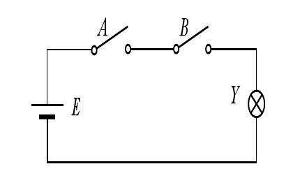
Logic refers to the causal relationship between things, or the relationship between conditions and results, which can be expressed using logic operations and Boolean algebra. Things often exist in two opposing states, which can be abstractly represented as 0 and 1 in Boolean algebra, known as logic 0 state and logic 1 state. Based on logic variables, the logical relationship can be described as a logic variable expression or equation and given a calculation or solution process, which is called logic algebra modeling. For example, Y = A & B & C; describes three input variables A, B, and C, and the output variable Y is only 1 when all three variables are 1. It can be seen that relationships described by logic equations are more general.
4.Logic Function:
If several logic variables (such as A, B, C, D, etc.) are combined together using the three basic operations of AND, OR, and NOT, and an expression L is obtained, which has a unique value corresponding to any set of values for the logic variables (such as 0000…, 0001…, 0010…), then L is called a logic function. The logic function of the logic variables A, B, C, D, etc. is denoted by L = f(A, B, C, D, …), where the logic variables A, B, C, D, etc. are independent variables, and L is the dependent variable or function. For example, Y = A & B.
5.Truth Table:
In addition to describing the input-output relationship using a logic function, it is also possible to describe the relationship between input and output variables using a table. Generally, all combinations of the input variables are listed on the left side of the table, and the corresponding outputs are listed on the right side. This table is called a truth table. The truth table can generally be obtained from a functional description table as following figures:
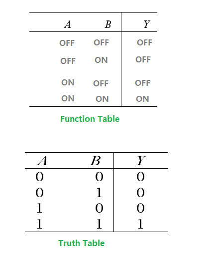
Although functional description table is very clear, it has a fatal flaw, which is that it is difficult to use mathematical tools for various calculations and deductions, and it is not convenient to generalize the research results.
Therefore, by converting the functional table into a truth table and combining it with a logic function, various analysis methods of logic algebra can be used to achieve simplification, extraction, and synthesis, and finally converted into RTL (register transfer level) logic circuits.