Computers perform billions of arithmetic operations every second.
But underneath CPUs, ALUs, registers, and complex instruction sets, arithmetic begins with a surprisingly simple question:
How can digital circuits add two binary bits?
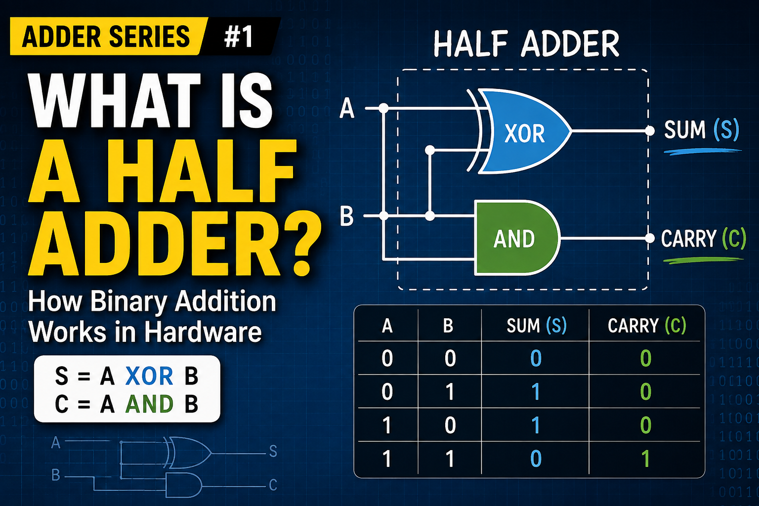
The simplest circuit that can do this is called a half adder.
A half adder takes two binary inputs and produces two outputs:
- Sum
- Carry
And remarkably, the basic circuit requires only two logic gates:
- an XOR gate
- an AND gate
Let us see why.
1. Start with Binary Addition
Before looking at the circuit, consider all possible additions of two binary bits.
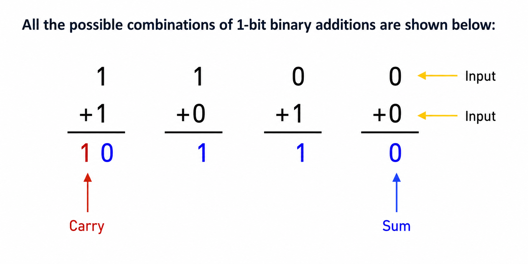
Since each bit can only be 0 or 1, there are only four possibilities:
0 + 0 = 0

0 + 1 = 1

1 + 0 = 1

1 + 1 = 10
The first three are straightforward.
But the last one is important:
1 + 1 = 10
The result requires two bits.
The right bit is the sum.
The left bit is the carry.
So a circuit that adds two bits cannot always produce only one output.
It needs two outputs.
2. Two Inputs and Two Outputs
Let the two input bits be:
A
B
The half adder produces:
S = Sum
C = Carry
Conceptually:
        ┌─────────────┐
A ─────►│             │────► S
        │ HALF ADDER  │
B ─────►│             │────► C
        └─────────────┘
So the problem is now simple:
What logic should generate S and C?
We can find the answer by examining every possible input combination.
3. The Half Adder Truth Table
The complete truth table is:
| A | B | Sum (S) | Carry (C) |
|---|---|---|---|
| 0 | 0 | 0 | 0 |
| 0 | 1 | 1 | 0 |
| 1 | 0 | 1 | 0 |
| 1 | 1 | 0 | 1 |
This small table contains everything we need to build the circuit.
Let us examine the two outputs separately.
4. Finding the Sum Circuit
First, ignore Carry and look only at the Sum column.
| A | B | S |
|---|---|---|
| 0 | 0 | 0 |
| 0 | 1 | 1 |
| 1 | 0 | 1 |
| 1 | 1 | 0 |
Notice the pattern.
The output is 1 when the two inputs are different.
0, 1 → 1

1, 0 → 1
But when the inputs are the same:
0, 0 → 0

1, 1 → 0
the output is 0.
This is exactly the behavior of an XOR gate.
Therefore:
S = A XOR B
Or in Boolean notation:
S = A ⊕ B
The Sum portion of our half adder is therefore simply:
A ─────┐
       ├──── XOR ─────► S
B ─────┘
We have already built half of the circuit.
5. Finding the Carry Circuit
Now look at the Carry column.
| A | B | C |
|---|---|---|
| 0 | 0 | 0 |
| 0 | 1 | 0 |
| 1 | 0 | 0 |
| 1 | 1 | 1 |
Carry becomes 1 only in one situation:
A = 1
B = 1
That is exactly the behavior of an AND gate.
Therefore:
C = A AND B
Or:
C = A · B
The Carry circuit is:
A ─────┐
       ├──── AND ─────► C
B ─────┘
Now we have both parts.
6. The Complete Half Adder Circuit
Combine the XOR and AND gates:
                 ┌──── XOR ─────► S
A ───────────────┤
                 │
                 │
B ───────────────┘


                 ┌──── AND ─────► C
A ───────────────┤
                 │
                 │
B ───────────────┘
Both gates receive the same two input bits.
The XOR gate generates the Sum.
The AND gate generates the Carry.
So the complete half adder can be described with just two equations:
S = A XOR B

C = A AND B
This is one of the simplest arithmetic circuits in digital electronics.
7. What Happens When A = 0 and B = 0?
Suppose:
A = 0
B = 0
The XOR gate produces:
S = 0
The AND gate produces:
C = 0
Therefore:
C S
0 0
which represents binary zero.
So:
0 + 0 = 00
8. What Happens When A = 0 and B = 1?
Now:
A = 0
B = 1
The XOR output is:
S = 1
The AND output is:
C = 0
Together:
C S
0 1
So:
0 + 1 = 01
which is decimal 1.
9. What Happens When A = 1 and B = 0?
Now reverse the inputs:
A = 1
B = 0
Again:
S = 1
C = 0
Therefore:
1 + 0 = 01
The circuit behaves exactly as expected.
10. What Happens When A = 1 and B = 1?
This is the most interesting case.
The XOR gate receives:
1 XOR 1
and produces:
S = 0
The AND gate receives:
1 AND 1
and produces:
C = 1
Together:
C S
1 0
So the result is:
10
which is decimal 2.
Therefore:
1 + 1 = 10
The circuit has successfully performed binary addition.
11. Why Is It Called a Half Adder?
At first, the half adder seems complete.
It can calculate every possible combination of:
A + B
So why is it called only a half adder?
Because real binary addition has another problem.
Consider adding two multi-bit numbers:
  11
+ 01
----
Start with the least significant bit:
1 + 1 = 10
We write 0 and carry 1 into the next column.
Now the next calculation is not simply:
1 + 0
It is:
1 + 0 + 1
The third 1 is the carry from the previous bit.
And here we discover the limitation of the half adder.
A half adder has only two inputs:
A
B
It has no input for the incoming carry.
In other words, it can calculate:
A + B
but it cannot directly calculate:
A + B + Carry-in
That limitation prevents us from simply using a half adder for every bit of a multi-bit addition.
12. Half Adder vs. Real Binary Addition
The half adder gives us an important first step.
It shows how logic gates can perform arithmetic.
The relationship is beautifully simple:
Binary Addition
      │
      ▼
 ┌───────────┐
 │Half Adder │
 └───────────┘
    │     │
    ▼     ▼
   XOR   AND
    │     │
    ▼     ▼
   Sum   Carry
There is no software involved.
There is no instruction being interpreted inside the half adder.
The electrical states representing 0 and 1 enter logic gates, and the circuit produces the correct binary result.
This is how arithmetic begins to emerge from digital logic.
13. From Logic Gates to Computer Arithmetic
The half adder is a very small circuit, but the idea behind it is fundamental.
Earlier, we learned that logic gates can implement Boolean operations.
Now those same gates are beginning to do something more interesting:
arithmetic.
An XOR gate and an AND gate together can add two bits.
But computers need to add much larger numbers:
8-bit
16-bit
32-bit
64-bit
To do that, the circuit must handle carries moving from one bit position to another.
And that requires one more input:
Carry-in
Once we add that third input, the half adder evolves into a much more useful circuit.
The full adder.
Conclusion
A half adder is the simplest digital circuit for adding two binary bits.
It has two inputs:
A
B
and two outputs:
Sum
Carry
The Sum output follows the XOR truth table:
S = A XOR B
The Carry output follows the AND truth table:
C = A AND B
Therefore, a basic half adder requires only:
1 XOR gate
+
1 AND gate
This tiny circuit demonstrates an important idea in computer architecture:
arithmetic can be constructed directly from logic gates.
But the half adder has one major limitation.
It cannot accept a carry from a previous bit.
To build an adder capable of handling multi-bit binary numbers, we need a circuit with three inputs:
A
B
Carry-in
That circuit is the full adder.
And that is where we will go next.