In the previous lesson, we learned how a half adder can add two binary bits.

A half adder takes two inputs:
A
B
and produces two outputs:
Sum
Carry
Using only two logic gates:
XOR → Sum
AND → Carry
That works perfectly when we are adding only two bits.
But real computers rarely add just one bit.
They add numbers containing many bits:
8-bit
16-bit
32-bit
64-bit
And once several bit positions are involved, a new problem appears.
A bit position may receive a carry from the previous position.
The half adder cannot handle that.
To solve this problem, we need a slightly more powerful circuit:
the full adder.
A full adder adds three one-bit inputs and produces a Sum and Carry-out.
1. The Problem with the Half Adder
Consider this binary addition:
   11
 + 01
 ----
Start with the rightmost column:
1 + 1 = 10
We write:
0
as the Sum and carry:
1
into the next column.
Now look at the next calculation.
It is not simply:
1 + 0
Instead, we must calculate:
1 + 0 + 1
The third bit is the carry from the previous column.
A half adder has only two inputs:
A
B
So it cannot accept that incoming carry.
This is exactly the problem the full adder solves. Full adders include a third input specifically so carries from less-significant bit positions can participate in the next addition.
2. Three Inputs, Two Outputs
A full adder has three inputs:
A
B
Cin
where:
Cin = Carry-in
It produces two outputs:
S    = Sum
Cout = Carry-out
Conceptually:
          ┌─────────────┐
A ───────►│             │
B ───────►│ FULL ADDER  │────► S
Cin ─────►│             │────► Cout
          └─────────────┘
The circuit calculates:
A + B + Cin
Because all three inputs are single bits, the largest possible calculation is:
1 + 1 + 1 = 3
In binary:
3 = 11
So once again, two output bits are enough:
Cout S
For:
1 + 1 + 1
we get:
Cout = 1
S    = 1
or:
11
A full adder therefore handles values from binary 000 through 111, producing a two-bit result.
3. The Full Adder Truth Table
With three binary inputs, there are:
2 × 2 × 2 = 8
possible input combinations.
The complete truth table is:
| A | B | Cin | Sum (S) | Carry-out (Cout) |
|---|---|---|---|---|
| 0 | 0 | 0 | 0 | 0 |
| 0 | 0 | 1 | 1 | 0 |
| 0 | 1 | 0 | 1 | 0 |
| 0 | 1 | 1 | 0 | 1 |
| 1 | 0 | 0 | 1 | 0 |
| 1 | 0 | 1 | 0 | 1 |
| 1 | 1 | 0 | 0 | 1 |
| 1 | 1 | 1 | 1 | 1 |
This truth table completely describes the behavior of the full adder.
Now we can examine the two outputs separately.
4. Finding the Sum
Look only at the Sum column:
| A | B | Cin | S |
|---|---|---|---|
| 0 | 0 | 0 | 0 |
| 0 | 0 | 1 | 1 |
| 0 | 1 | 0 | 1 |
| 0 | 1 | 1 | 0 |
| 1 | 0 | 0 | 1 |
| 1 | 0 | 1 | 0 |
| 1 | 1 | 0 | 0 |
| 1 | 1 | 1 | 1 |
Notice something interesting.
The Sum is 1 whenever an odd number of inputs are 1.
That is exactly what chained XOR operations produce.
Therefore:
S = A XOR B XOR Cin
or in Boolean notation:
S = A ⊕ B ⊕ Cin
We can calculate it in two stages:
X = A XOR B
S = X XOR Cin
This observation gives us the first clue about how to build the circuit.
5. Finding the Carry-Out
Now look at Carry-out:
| A | B | Cin | Cout |
|---|---|---|---|
| 0 | 0 | 0 | 0 |
| 0 | 0 | 1 | 0 |
| 0 | 1 | 0 | 0 |
| 0 | 1 | 1 | 1 |
| 1 | 0 | 0 | 0 |
| 1 | 0 | 1 | 1 |
| 1 | 1 | 0 | 1 |
| 1 | 1 | 1 | 1 |
Carry-out becomes 1 whenever at least two of the three inputs are 1.
For example:
0 + 1 + 1 = 10
so:
S    = 0
Cout = 1
Likewise:
1 + 1 + 0 = 10
and:
1 + 1 + 1 = 11
both produce a Carry-out.
One common Boolean expression is:
Cout = AB + ACin + BCin
But there is another form that maps very naturally onto the circuit:
Cout = (A AND B)
       OR
       (Cin AND (A XOR B))
This form helps us see how the full adder can be constructed from half adders.
6. Building a Full Adder from Two Half Adders
Here is one of the most important ideas in this lesson.
A full adder does not need to be invented from scratch.
We can build it from components we already understand:
2 Half Adders
+
1 OR Gate
This is a standard way to construct a full adder.
The process happens in two stages.
First Half Adder
The first half adder adds:
A + B
It produces:
X  = A XOR B
C1 = A AND B
So:
A ─────┐
       ├──► HALF ADDER 1 ───► X
B ─────┘                 └──► C1
But we are not finished.
We still have:
Cin
to add.
7. The Second Half Adder
The second half adder takes:
X
Cin
as its two inputs.
Remember:
X = A XOR B
The second half adder now calculates:
X + Cin
It produces:
S  = X XOR Cin
C2 = X AND Cin
Therefore:
S = (A XOR B) XOR Cin
which gives us:
S = A XOR B XOR Cin
This is the final Sum output.
The source circuit follows exactly this arrangement: the Sum output from the first half adder feeds the second half adder together with Cin.
8. Why Do We Need the OR Gate?
We now have two possible carry signals:
C1
C2
The first half adder may produce a carry:
C1 = A AND B
And the second half adder may also produce a carry:
C2 = Cin AND (A XOR B)
Either one means the full addition needs a Carry-out.
So we combine them with an OR gate:
Cout = C1 OR C2
The complete idea is:

          ┌───────────────┐
A ───────►│               │
          │ HALF ADDER 1  │───► X ───────┐
B ───────►│               │              │
          └───────────────┘              ▼
                 │               ┌───────────────┐
                 │ C1            │               │
                 │         Cin ─►│ HALF ADDER 2  │───► S
                 │               │               │
                 │               └───────────────┘
                 │                       │
                 │                       │ C2
                 ▼                       ▼
              ┌────────────────────────────┐
              │           OR               │
              └────────────────────────────┘
                           │
                           ▼
                         Cout
So the full adder contains:
2 XOR gates
2 AND gates
1 OR gate
in this straightforward implementation.
9. Walking Through an Example
Suppose:
A   = 1
B   = 0
Cin = 1
We want to calculate:
1 + 0 + 1
which equals:
10
First Half Adder
Calculate:
A XOR B
so:
1 XOR 0 = 1
Therefore:
X = 1
The first carry is:
1 AND 0 = 0
so:
C1 = 0
Second Half Adder
Now add:
X + Cin
or:
1 + 1
The Sum becomes:
1 XOR 1 = 0
and the second carry becomes:
1 AND 1 = 1
Therefore:
S  = 0
C2 = 1
Finally:
Cout = C1 OR C2
so:
0 OR 1 = 1
The final result is:
Cout S
  1  0
or:
10
Exactly what we expected.
10. Half Adder vs. Full Adder
The difference between the two circuits is now clear.
Half Adder
Inputs:
A
B
Outputs:
Sum
Carry
It calculates:
A + B
Full Adder
Inputs:
A
B
Cin
Outputs:
Sum
Cout
It calculates:
A + B + Cin
The key difference is therefore not simply that the full adder contains more gates.
The important difference is:
the full adder can accept a carry from a previous bit position.
That capability makes it useful for multi-bit arithmetic.
11. From One Full Adder to Multi-Bit Addition
Now we can see why the full adder is so important.
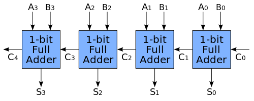
Suppose we want to add two 4-bit numbers:
A3 A2 A1 A0
B3 B2 B1 B0
We can use one full adder for each bit position.
Conceptually:
A0 ─┐
B0 ─┼──► FA0 ──Cout──► FA1 ──Cout──► FA2 ──Cout──► FA3
Cin ─┘
More completely:
A0,B0 ─► FA0 ─► S0
            │
            ▼ Carry

A1,B1 ─► FA1 ─► S1
            │
            ▼ Carry

A2,B2 ─► FA2 ─► S2
            │
            ▼ Carry

A3,B3 ─► FA3 ─► S3
            │
            ▼
         Final Carry
The Carry-out from one stage becomes the Carry-in of the next stage.
This arrangement allows several one-bit adders to work together to add complete binary numbers. The reference circuit demonstrates the same idea with a 4-bit adder, where each stage passes its carry into the next more-significant stage.
This is where a tiny logic circuit begins to grow into something much closer to the arithmetic hardware inside a processor.
12. Why the Full Adder Matters
A full adder may look like a very small circuit.
But conceptually, it solves one of the most important problems in binary arithmetic:
how to propagate information from one bit position to another.
A single full adder handles one bit.
Multiple full adders can handle many bits.
This gives us a path from:
Logic Gates
     │
     ▼
Half Adder
     │
     ▼
Full Adder
     │
     ▼
Multi-Bit Adder
     │
     ▼
Computer Arithmetic
We started with individual Boolean operations.
Now those operations are being connected together to perform arithmetic on complete binary numbers.
Conclusion
A full adder is a digital circuit that adds three one-bit inputs:
A
B
Cin
and produces two outputs:
Sum
Cout
The Sum is:
S = A XOR B XOR Cin
The Carry-out can be written as:
Cout = (A AND B)
       OR
       (Cin AND (A XOR B))
A straightforward full adder can be constructed from:
2 Half Adders
+
1 OR Gate
The first half adder adds A and B.
The second half adder adds the first Sum to Cin.
The OR gate combines the two possible carry signals into the final Cout.
The most important improvement over the half adder is the Carry-in input.
Because one full adder can receive a carry from another full adder, these circuits can be connected together to add multi-bit binary numbers.
And that leads directly to our next question:
What happens when we connect several full adders together?
The answer is the ripple-carry adder.