1. What Is an Integrated Circuit?
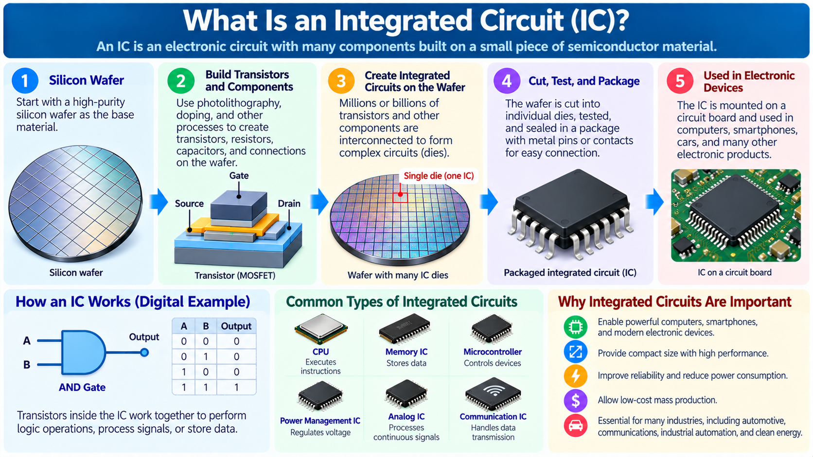
An integrated circuit, commonly called an IC, is an electronic circuit in which multiple components are fabricated and interconnected on or within a small piece of semiconductor material.
These components may include transistors, diodes, resistors, capacitors, and conductive connections that work together to perform specific electronic functions.
Integrated circuits are fundamental building blocks of modern electronic equipment.
They are used in computers, smartphones, automobiles, communication systems, industrial machines, medical devices, and household appliances.
For example, a computer processor is a highly complex integrated circuit designed to execute instructions and process information.
A memory IC stores data, while a voltage regulator IC controls electrical power supplied to other components.
An IC may contain only a relatively small number of components, or it may integrate billions of transistors into an extremely complex system.
The term integrated is important because the components are manufactured together rather than assembled individually as separate parts on a circuit board.
Before integrated circuits became practical, electronic systems often required large numbers of discrete transistors, resistors, capacitors, and wires.
These systems were physically larger and more difficult to manufacture and maintain.
Integrated circuits made it possible to place complex electronic functionality into compact, reliable, and economically manufacturable devices.
Understanding ICs is essential for learning electronics, digital logic, computer architecture, microcontrollers, semiconductor manufacturing, and modern chip design.
2. What Does IC Stand For?
IC stands for Integrated Circuit.
An electronic circuit is a collection of connected components arranged to perform a function.
For example, a simple circuit may contain a resistor, capacitor, transistor, and power source.
An integrated circuit combines multiple circuit elements into a single manufactured semiconductor structure.
The word circuit refers to the electrical arrangement that performs the function, while integrated describes the way the components are manufactured together.
In everyday electronics, the term IC is often used interchangeably with chip or microchip.
For example, an engineer may refer to a memory IC, an amplifier IC, a logic IC, or a processor chip.
However, the terminology has some important distinctions.
An integrated circuit describes the electronic device and its circuitry.
A die is the actual piece of semiconductor material containing the fabricated circuit.
The package provides protection and external electrical connections.
A modern semiconductor package may contain one integrated circuit die or multiple interconnected dies.
Therefore, an integrated circuit is not necessarily identical to the complete packaged component that a user sees on a circuit board.
3. Why Were Integrated Circuits Invented?
Before integrated circuits were developed, electronic systems were built using individual components.
Early electronic computers used large numbers of vacuum tubes.
Vacuum tubes could perform switching and amplification, but they were relatively large, consumed substantial power, and generated significant heat.
Transistors gradually replaced vacuum tubes in many applications because they were smaller, generally more reliable, and more energy-efficient.
However, building complex electronic systems using individual transistors still required extensive wiring and assembly.
Every component needed electrical connections to other components.
As circuit complexity increased, the number of connections also increased.
This created manufacturing difficulties, higher costs, and more opportunities for connection failures.
Integrated circuits addressed these problems by manufacturing multiple electronic components together on semiconductor material.
The development of practical integrated circuits is associated with the work of Jack Kilby at Texas Instruments in 1958 and Robert Noyce at Fairchild Semiconductor in 1959.
Their contributions helped establish the foundations of modern integrated circuit technology.
Over subsequent decades, improvements in semiconductor fabrication allowed increasingly complex circuits to be integrated into smaller areas.
This development transformed electronics and made modern computing possible.
4. What Is Inside an Integrated Circuit?
The internal structure of an integrated circuit depends on its function.
A simple analog IC may contain transistors, resistors, capacitors, current sources, and other circuit elements.
A digital IC may contain logic gates, flip-flops, registers, memory arrays, arithmetic circuits, and control logic.
A mixed-signal IC combines analog and digital circuitry.
For example, an analog-to-digital converter may contain analog input circuits, sampling structures, comparators, reference circuits, and digital control logic.
Most modern digital ICs are built primarily from transistor-based circuits.
Transistors control electrical behavior and allow circuits to switch between logical states.
The transistors are connected through conductive structures manufactured above the semiconductor device layers.
Modern ICs may contain many layers of metal interconnections separated by insulating materials.
These connections distribute power, carry data, and connect functional blocks.
The physical structure is extremely compact.
A processor die only a few centimeters across may contain billions of transistors and an enormous network of electrical connections.
However, not every integrated circuit is large or complex. Many useful ICs contain relatively simple circuits designed for one specific function.
5. How Does an Integrated Circuit Actually Work?
An integrated circuit works by controlling electrical signals through a carefully designed network of electronic components.
The specific behavior depends on the circuit design.
For example, a digital logic IC processes electrical signals representing binary values.
A voltage near the lower supply rail may represent logic 0, while a voltage near the upper supply rail may represent logic 1.
Transistors within the IC control how these signals influence the outputs.
A simple logic gate may perform an AND, OR, NOT, or XOR operation.
More complex digital circuits combine many gates to perform arithmetic, store information, and control data movement.
An analog IC operates differently.
Instead of processing only two logical states, an analog circuit may amplify, filter, compare, or regulate continuously varying signals.
For example, an operational amplifier IC can amplify the voltage difference between two input terminals when connected in an appropriate feedback circuit.
A power management IC may regulate an output voltage by controlling switching devices and monitoring feedback signals.
The common principle is that the IC’s internal circuit structure determines how it responds to electrical inputs and produces outputs.
An IC does not need to contain a processor or execute software. Many integrated circuits perform their functions entirely through dedicated hardware.
6. What Is the Difference Between an IC and a Transistor?
A transistor is an individual semiconductor device used to control electrical current or voltage.
An integrated circuit is a larger electronic structure that combines multiple components to perform useful functions.
For example, a MOSFET can act as an electronic switch.
Several MOSFETs can be combined to create a logic gate.
Multiple logic gates can form an adder, counter, or control circuit.
Thousands or millions of these circuits may then be integrated into a larger device.
A modern IC can contain anything from a small collection of transistors to billions of them.
However, transistors are not the only components that can exist within an IC.
Analog and mixed-signal circuits may also contain integrated resistors, capacitors, diodes, and other devices.
The relationship can be summarized as a hierarchy: transistors and other electronic components form circuits, and integrated circuits combine these components into functional electronic systems.
A transistor is therefore a building block, while an IC is a manufactured circuit containing interconnected building blocks.
7. What Is the Difference Between an IC and a Computer Chip?
In everyday usage, IC and chip often refer to the same kind of electronic device.
However, the word chip can have several meanings depending on the context.
In semiconductor manufacturing, a chip may refer to the semiconductor die containing the integrated circuit.
In consumer electronics, people often call the complete packaged component a chip.
For example, a CPU installed on a motherboard is commonly called a processor chip.
The actual electronic circuitry is fabricated on one or more semiconductor dies inside its package.
An IC describes the integrated electronic circuit itself.
A chip may refer to the physical die or the packaged product containing the circuitry.
Another important distinction is that not every semiconductor chip is a digital computer processor.
Many chips are analog ICs, power management devices, memory devices, communication circuits, or specialized controllers.
Therefore, all CPUs are implemented using integrated circuit technology, but not all integrated circuits are CPUs.
8. What Materials Are Used to Make ICs?
Silicon is the most widely used semiconductor material for modern integrated circuits.
Silicon is useful because its electrical properties can be controlled through doping and transistor structures.
Doping introduces carefully selected impurity atoms into semiconductor material.
For example, phosphorus can be used as a donor dopant in silicon, while boron can be used as an acceptor dopant.
These impurities create semiconductor regions with different concentrations of electrons and holes.
Such regions are important for manufacturing transistors, diodes, and other devices.
An integrated circuit also contains materials beyond the semiconductor substrate.
Conductive materials provide electrical interconnections.
Insulating materials separate different conducting structures.
Specialized dielectric materials are used in transistor gate structures and other circuit elements.
Modern semiconductor devices may also use complex metal stacks and additional materials to meet electrical and manufacturing requirements.
Although silicon dominates general-purpose digital IC production, other semiconductor materials are important in particular applications.
Examples include gallium arsenide, gallium nitride, and silicon carbide.
The best material depends on the electrical, optical, thermal, and manufacturing requirements of the device.
9. What Are Logic Gates in an Integrated Circuit?
A logic gate is a circuit that performs a defined operation on digital input signals.
Logic gates are fundamental building blocks of digital integrated circuits.
Common examples include AND, OR, NOT, NAND, NOR, and XOR gates.
An AND gate produces logic 1 when all required inputs are 1.
An OR gate produces logic 1 when at least one input is 1.
A NOT gate reverses its input.
An XOR gate produces logic 1 when two inputs differ.
These operations are implemented using transistor circuits.
For example, a conventional CMOS inverter uses one p-channel transistor and one n-channel transistor.
By combining logic gates, engineers can create more complicated circuits.
A binary adder performs arithmetic.
A comparator checks relationships between binary numbers.
A multiplexer selects one of several inputs.
A decoder converts encoded information into control signals.
Larger groups of logic circuits form arithmetic units, controllers, memory interfaces, and other digital systems.
The ability to manufacture enormous numbers of logic gates on a small die is one of the foundations of modern computing.
10. What Is the Difference Between Analog and Digital ICs?
Integrated circuits can be classified according to the types of signals they process.
Digital ICs primarily operate using discrete logical states.
For example, a digital counter receives clock signals and changes its stored binary value according to its internal logic.
Digital processors, many memory devices, and logic ICs are examples of digital integrated circuits.
Analog ICs process signals that can vary continuously over a range of voltages or currents.
Examples include operational amplifiers, analog filters, reference circuits, and some voltage regulators.
An analog amplifier may increase the amplitude of a small electrical signal.
A filter may reduce unwanted frequency components.
A voltage reference generates a controlled electrical reference used by other circuits.
The distinction between analog and digital circuits is important because their design methods and performance requirements differ.
Digital circuit design often emphasizes logic functionality, timing, and state transitions.
Analog circuit design frequently emphasizes gain, bandwidth, noise, distortion, matching, and signal accuracy.
Both categories are essential in modern electronic systems.
11. What Is a Mixed-Signal Integrated Circuit?
A mixed-signal IC combines analog and digital circuitry within the same integrated device.
This is useful because real-world signals are often analog, while many computing and control systems process digital data.
For example, a temperature sensor may generate a voltage that changes with temperature.
A digital processor cannot directly interpret every continuously varying voltage as a numerical measurement.
An analog-to-digital converter, or ADC, converts the analog signal into a digital representation.
A digital-to-analog converter, or DAC, performs the reverse operation by converting digital values into corresponding analog signals.
Mixed-signal ICs are common in communication equipment, audio systems, industrial controllers, sensors, and consumer electronics.
A smartphone may contain mixed-signal circuits for audio processing, wireless communication, and power management.
These devices require careful integration because digital switching activity can introduce electrical noise that interferes with sensitive analog circuits.
Engineers use suitable layout, isolation, grounding, power distribution, and circuit techniques to manage these interactions.
12. What Are the Main Types of Integrated Circuits?
Integrated circuits can be grouped according to their functions.
Logic ICs implement digital operations such as gates, counters, registers, and decoders.
Processor ICs execute instructions and perform general-purpose or specialized computation.
Memory ICs store digital information.
Analog ICs amplify, regulate, filter, or otherwise process analog signals.
Mixed-signal ICs combine analog and digital functions.
Power management ICs control and regulate electrical power.
Communication ICs provide signal processing and interfaces for wired or wireless data transfer.
Sensor ICs measure physical conditions such as light, temperature, pressure, motion, or magnetic fields.
Application-specific integrated circuits are designed for particular functions.
These categories can overlap.
For example, a microcontroller contains processing logic, memory, digital peripherals, and sometimes analog interfaces.
A smartphone SoC may combine CPU cores, GPU resources, image processing, neural network acceleration, and communication controllers.
The function of an IC depends on the architecture and circuitry implemented within it.
13. What Is a Logic IC?
A logic IC is an integrated circuit designed to perform digital logic operations.
Early digital systems frequently used separate logic ICs for functions such as gates, counters, registers, and multiplexers.
Many of these devices were manufactured in standard logic families.
Examples include the 7400 series of digital logic integrated circuits.
A classic 7400 device contains four two-input NAND gates.
A 7404 device contains six inverter gates.
Other members of the logic family provide counters, latches, flip-flops, buffers, and additional functions.
These devices are still useful for education, circuit design, signal conditioning, and specialized hardware applications.
For example, a small digital circuit may use a logic IC to combine several control signals.
However, modern processors and programmable devices often integrate enormous quantities of logic within one package.
Understanding simple logic ICs remains valuable because they illustrate how larger digital systems are constructed.
14. What Is a Memory IC?
A memory IC stores information using semiconductor circuits.
Different memory technologies use different physical storage mechanisms and provide different performance characteristics.
SRAM, or Static Random Access Memory, commonly uses transistor-based storage cells that maintain their state while power is supplied.
SRAM is widely used in processor caches and other high-speed memory structures.
DRAM, or Dynamic Random Access Memory, generally stores information using electrical charge in capacitive memory cells.
The stored charge gradually leaks away, so DRAM requires periodic refresh operations.
DRAM is widely used as the main system memory in computers and servers.
Flash memory is a nonvolatile semiconductor memory technology that retains stored information without continuous power.
NAND flash is widely used in solid-state drives, smartphones, and removable storage devices.
These memory types involve trade-offs involving speed, density, cost, endurance, power consumption, and data retention.
A computer may use several memory technologies because no single type is optimal for every purpose.
15. What Is a Processor IC?
A processor IC contains circuitry designed to execute instructions or perform defined computational tasks.
A CPU is a general-purpose processor used for operating systems, applications, control functions, and other software workloads.
A GPU is a processor designed to provide high throughput for graphics and suitable parallel computations.
A microcontroller typically combines a processing core, memory, and peripheral functions in an integrated device intended for embedded control.
Modern processors may contain billions of transistors.
These transistors form registers, arithmetic units, caches, instruction decoders, control circuitry, and other structures.
When a CPU executes an instruction, the internal circuits coordinate data movement and computation according to the instruction set architecture.
For example, an addition instruction may cause operands to be read from registers, processed by an arithmetic unit, and written back to a destination register.
A processor’s flexibility comes from its ability to execute different instruction sequences without changing its physical circuit design.
However, processors vary greatly in architecture, performance, energy consumption, and intended applications.
16. What Is an ASIC?
ASIC stands for Application-Specific Integrated Circuit.
An ASIC is an integrated circuit designed for a particular application or class of functions.
Unlike a general-purpose CPU, which can execute many kinds of software, an ASIC may implement specialized operations directly in dedicated hardware.
For example, an ASIC may accelerate network packet processing, video encoding, machine learning calculations, or cryptographic functions.
Specialized circuits can reduce unnecessary instruction processing and data movement for suitable workloads.
This can improve performance or energy efficiency compared with a general-purpose implementation.
However, ASIC development involves substantial engineering work.
The design must be verified and manufactured, and mistakes can be expensive to correct after fabrication.
ASICs may still contain programmable processors, firmware, memory, and configurable control registers.
Therefore, ASIC does not necessarily mean that every aspect of the chip is permanently fixed.
The term describes the application’s specialized design objective rather than the absence of all programmability.
17. What Is the Difference Between an IC and an FPGA?
An FPGA, or Field-Programmable Gate Array, is itself a type of integrated circuit.
The important difference is that an FPGA contains configurable logic resources and programmable interconnections.
Engineers can use configuration data to define the digital circuits implemented within the available FPGA resources.
For example, an FPGA can be configured to implement counters, communication controllers, digital signal processing circuits, or even a processor core.
Many FPGAs can be reconfigured multiple times.
By contrast, the functional transistor-level structure of a conventional fixed-function ASIC is established during manufacturing.
A CPU can execute different software programs without changing its physical logic structure, while an FPGA can change the configuration of its digital hardware resources.
FPGAs are useful for prototyping, hardware acceleration, interface development, and applications requiring flexible digital logic.
However, they generally have different performance, power, cost, and development trade-offs from ASICs.
An FPGA is therefore not an alternative to integrated circuit technology. It is one particular category of integrated circuit.
18. What Is the Difference Between an IC and an SoC?
SoC stands for System on Chip.
An SoC is an integrated circuit that combines several major system functions into one chip or chip-level system.
For example, a smartphone application processor may include CPU cores, GPU resources, memory controllers, image processing hardware, display interfaces, and specialized accelerators.
A microcontroller can also be considered a form of highly integrated system-oriented device because it combines processing, memory, and peripherals.
The term IC is broader.
An IC may perform only one simple function, such as voltage regulation or logic inversion.
An SoC combines multiple functions that would otherwise require separate devices.
However, the boundary between an ordinary IC and an SoC is not always strict.
Many modern chips integrate several functional blocks, and manufacturers may use different terminology depending on the product.
The key distinction is the degree of system-level integration.
19. How Are Integrated Circuits Designed?
Integrated circuit design begins with defining the required functionality and engineering constraints.
For example, an IC project may specify operating voltage, performance, power consumption, interface requirements, chip area, reliability, and manufacturing cost.
The design process depends on whether the circuit is digital, analog, or mixed-signal.
For digital ICs, engineers commonly use hardware description languages such as Verilog, SystemVerilog, or VHDL.
These languages describe circuit behavior, registers, control logic, and other digital structures.
A design may be developed at the Register Transfer Level, or RTL.
RTL describes how data moves between registers and how combinational logic processes it.
Simulation and formal verification tools help engineers determine whether the design behaves correctly.
Logic synthesis converts suitable RTL into a gate-level implementation using standard cells from a semiconductor technology library.
Physical design tools then place the cells and create the electrical interconnections.
Analog IC design typically involves transistor-level circuit design, simulation, device modeling, and carefully controlled physical layout.
Mixed-signal IC design combines both approaches.
After verification and physical design, manufacturing data is prepared for fabrication.
20. What Is RTL in IC Design?
RTL stands for Register Transfer Level.
It is a common abstraction used in digital hardware design.
At the RTL level, engineers describe how registers store information and how combinational logic transforms data between registers.
For example, a digital counter can be described as a register whose value increases under certain clock and control conditions.
The RTL description specifies the intended behavior of the circuit.
It does not necessarily identify every individual transistor.
Electronic design automation tools can convert the RTL into a network of logic cells suitable for a selected semiconductor process.
For example, a simple RTL addition operation may be implemented using an appropriate combination of arithmetic logic cells.
The final implementation depends on timing constraints, area targets, power requirements, and the available cell library.
RTL is used in ASIC development and FPGA design.
However, the final physical implementation differs.
An ASIC flow maps the design into cells manufactured on a semiconductor die, while an FPGA flow maps it into existing programmable hardware resources.
Understanding RTL is therefore useful for anyone studying digital IC design.
21. What Is a Standard Cell?
A standard cell is a predesigned and characterized circuit block used in many digital ASIC implementations.
Standard cells typically implement functions such as inverters, NAND gates, NOR gates, flip-flops, buffers, and other logic or sequential operations.
A semiconductor technology library contains many standard cell types.
Each cell has defined electrical and physical characteristics.
These may include area, delay, power consumption, input capacitance, and other timing properties.
During synthesis, design tools map a logical circuit into suitable standard cells.
Physical design tools place those cells and connect them through metal routing.
This allows engineers to design large circuits without manually drawing every transistor.
However, not every IC is built entirely from standard cells.
Processors and other complex chips may also contain custom SRAM arrays, analog blocks, specialized arithmetic circuits, and hard macros.
Standard cell design is one of the foundations of modern digital ASIC development.
22. How Is an Integrated Circuit Manufactured?
Integrated circuits are manufactured using a sequence of semiconductor fabrication processes.
The process normally begins with a semiconductor wafer.
A wafer is a thin slice of highly purified crystalline material, commonly silicon.
Many copies of an IC design can be fabricated on a single wafer.
Manufacturing involves repeated operations such as lithography, deposition, etching, ion implantation, oxidation, and polishing.
Photolithography defines patterns used to create semiconductor devices and interconnections.
Deposition adds thin layers of materials.
Etching removes selected material.
Ion implantation introduces dopants into semiconductor regions.
Chemical mechanical polishing helps produce surfaces suitable for further manufacturing steps.
These operations are repeated many times to create transistors, isolation structures, contacts, and metal interconnect layers.
Modern manufacturing requires extremely precise process control.
Small defects can affect electrical behavior or prevent a die from functioning correctly.
After fabrication, the wafer undergoes testing and is separated into individual dies.
The dies are then packaged and tested according to the product requirements.
23. What Is Photolithography in IC Manufacturing?
Photolithography is a semiconductor manufacturing technique used to transfer patterns onto a wafer.
The process typically involves applying a light-sensitive material called photoresist.
An optical system exposes selected regions according to the required pattern.
After development, portions of the photoresist remain while others are removed.
The patterned photoresist can then help define areas for etching, implantation, or other processing steps.
Modern semiconductor manufacturing uses sophisticated lithography systems capable of creating extremely fine patterns.
Different process generations may use deep ultraviolet or extreme ultraviolet lithography for particular manufacturing layers.
Lithography is only one part of the fabrication process.
The finished IC requires many additional operations to form semiconductor devices and electrical connections.
Nevertheless, lithography is critically important because it helps define the geometric patterns used throughout the chip.
The precision, cost, and complexity of lithography are major factors in advanced semiconductor manufacturing.
24. What Is an IC Die?
An IC die is the individual piece of semiconductor material containing the fabricated integrated circuit.
During wafer manufacturing, many copies of a design are produced on a single wafer.
After fabrication and appropriate testing, the wafer is divided into individual dies.
This separation process is commonly called dicing or singulation.
The size of a die depends on the circuit complexity, manufacturing process, and design requirements.
A small control IC may use a relatively small die.
A high-performance processor or accelerator may require a much larger die or a multi-die architecture.
The die contains active semiconductor devices and the interconnections required for its operation.
However, an unpackaged die is not normally convenient for ordinary circuit board assembly.
It must be connected to the outside system and protected against mechanical and environmental damage.
This is the purpose of IC packaging.
25. What Is IC Packaging?
IC packaging provides electrical connections, mechanical protection, and thermal paths between the semiconductor die and the outside system.
A packaged IC may contain one die or multiple dies.
The package connects the die to external pins, pads, balls, or other terminals.
Different packaging methods include wire bonding and flip-chip interconnection.
In wire bonding, fine wires connect die pads to package connections.
In flip-chip packaging, the die is mounted face-down and connected using suitable bumps or other interconnect structures.
The package may use plastic, ceramic, organic substrates, metal structures, or combinations of materials.
Packaging must account for electrical performance, mechanical reliability, heat dissipation, cost, and manufacturing requirements.
For high-power processors, the package also helps transfer heat toward a cooling system.
Modern advanced packaging techniques can connect multiple dies with high-density interconnections.
Packaging is therefore an important engineering discipline rather than simply placing a protective cover over silicon.
26. What Are DIP, QFP, QFN, and BGA Packages?
Integrated circuits are available in many different package types.
DIP stands for Dual In-line Package.
A DIP package has two parallel rows of pins and is commonly associated with traditional through-hole circuit board assembly.
DIP ICs remain popular in electronics education because they can often be used with breadboards and sockets.
QFP stands for Quad Flat Package.
A QFP package has leads extending from its four sides.
QFN stands for Quad Flat No-lead.
QFN packages use contact pads, typically located around the underside edges, rather than long external leads.
BGA stands for Ball Grid Array.
A BGA package uses an array of solder balls on the underside of the package to connect to the circuit board.
BGA packaging is widely used for devices requiring many electrical connections, including processors, memory devices, and other complex ICs.
Each package type has different advantages and limitations involving size, pin count, assembly, inspection, repairability, and thermal behavior.
The appropriate package depends on the IC’s electrical and mechanical requirements.
27. What Are IC Pins?
IC pins or terminals provide electrical connections between the integrated circuit and external components.
Some pins supply electrical power.
Others provide ground connections, input signals, output signals, clocks, control signals, or communication interfaces.
For example, a simple logic IC may have pins for its power supply and ground, along with input and output pins for its logic gates.
A microcontroller may have many pins assigned to GPIO, communication interfaces, analog inputs, clocks, reset functions, and power.
GPIO stands for General-Purpose Input/Output.
A GPIO pin can often be configured to read a digital signal or drive an output.
However, not every pin is interchangeable.
Some pins have fixed electrical functions, while others support several alternative functions.
Connecting a pin incorrectly can cause the IC to malfunction or become damaged.
Engineers therefore use datasheets to identify the correct pin functions, voltage requirements, and electrical limits.
28. How Do You Read an IC Datasheet?
An IC datasheet is a technical document describing the characteristics and requirements of an integrated circuit.
It is one of the most important references when designing an electronic system.
A datasheet usually identifies the device’s intended function and main features.
It may provide a block diagram showing the internal functional organization.
The pin configuration section explains the purpose of each external connection.
Electrical characteristics describe operating voltages, currents, timing, and other parameters.
Absolute maximum ratings identify stress limits that must not be exceeded.
These ratings should not be confused with recommended normal operating conditions.
Timing diagrams explain relationships between signals.
For digital interfaces, the datasheet may specify setup times, hold times, clock frequency limits, and propagation delays.
For analog ICs, important parameters may include gain, bandwidth, offset voltage, noise, and distortion.
Power management datasheets may describe efficiency, load regulation, protection features, and thermal behavior.
Learning to read datasheets is essential for practical IC and circuit board design.
29. What Is the Difference Between an IC and a PCB?
A printed circuit board, or PCB, is a structure used to mount and electrically connect electronic components.
An integrated circuit contains electronic circuitry fabricated on semiconductor material.
The PCB provides a larger-scale network of conductive traces, pads, vias, and insulating layers.
For example, a computer motherboard contains processor packages, memory devices, power circuits, connectors, and other components.
Copper traces on the motherboard connect these devices.
Inside each integrated circuit, much smaller semiconductor devices and interconnections perform the actual electronic functions.
An IC can contain millions or billions of transistors within a small package.
A PCB connects multiple packaged components into a complete electronic system.
Therefore, an IC and a PCB are complementary rather than competing technologies.
The IC provides integrated electronic functionality, while the PCB supports assembly, electrical connections, power distribution, and mechanical integration.
30. What Is a Discrete Electronic Component?
A discrete electronic component is an individual component that performs a relatively limited electronic function.
Examples include resistors, capacitors, diodes, and individual transistors.
These components are manufactured separately and connected together when building circuits.
An integrated circuit combines multiple electronic components into a common manufactured device.
For example, an electronic amplifier could be built using separate transistors, resistors, and capacitors.
Alternatively, an operational amplifier IC could provide much of the amplifier functionality in one package.
Discrete components remain important even in systems containing advanced integrated circuits.
For example, an IC may require external capacitors for power supply decoupling.
A power converter may use discrete inductors and capacitors alongside a controller IC and power switches.
High-power transistors may also be implemented as separate packaged devices.
Modern electronics commonly use a combination of integrated circuits and discrete components.
31. Why Are Integrated Circuits So Small?
Integrated circuits are compact because their components are fabricated using semiconductor manufacturing processes rather than assembled as separate macroscopic devices.
Photolithography and related techniques allow tiny transistor structures and interconnections to be created on semiconductor wafers.
Many circuit elements can therefore occupy a small area.
Integration reduces the need for large numbers of external component connections.
It can also reduce certain wiring distances and associated parasitic effects.
However, smaller is not always better in every respect.
Advanced manufacturing processes are expensive, and very dense circuits create challenges involving power distribution, heat removal, leakage, and interconnect delay.
Some analog, power, or high-voltage applications require relatively large device structures.
The size of an IC therefore depends on the required function, operating conditions, manufacturing technology, and economic constraints.
32. Why Are Integrated Circuits More Reliable Than Large Discrete Circuits?
Integrated circuits can provide reliability advantages because many components and connections are manufactured together.
A traditional circuit assembled from numerous separate components may require many solder joints and external wires.
Every physical connection introduces another possible point of failure.
By integrating much of the circuitry onto a semiconductor die, engineers can reduce the number of external interconnections required for a given function.
Integrated circuits are also manufactured under tightly controlled processes.
However, ICs are not immune to failures.
Semiconductor devices can be damaged by excessive voltage, temperature, current, electrostatic discharge, manufacturing defects, or long-term wear mechanisms.
Complex ICs also require extensive testing and qualification.
Reliability depends on device design, fabrication quality, packaging, operating conditions, and system-level protection.
The advantage of integration is not that failures become impossible, but that complex functionality can be manufactured with fewer external component connections and highly repeatable processes.
33. Why Are Integrated Circuits Energy Efficient?
Integrated circuits can provide energy efficiency advantages through short internal connections, optimized transistor structures, and specialized circuit architectures.
For example, a modern CMOS logic circuit generally consumes relatively little static power in an idealized stable state compared with some older logic technologies.
Most dynamic CMOS power consumption is associated with charging and discharging electrical capacitances during switching.
A simplified relationship is:
P ≈ αCV²f
In this expression, P represents dynamic power, α is a switching activity factor, C is the effective switched capacitance, V is the supply voltage, and f is the switching frequency.
The equation illustrates why operating voltage, circuit activity, and clock frequency influence power consumption.
However, total power also includes leakage and other losses.
Integrated circuits may be designed to minimize energy per operation rather than simply maximize speed.
For example, a specialized accelerator can sometimes perform a repetitive operation more efficiently than a general-purpose processor.
Nevertheless, not every IC consumes little power.
High-performance CPUs, GPUs, and power ICs can dissipate substantial energy and require significant thermal management.
34. Why Do Integrated Circuits Generate Heat?
Integrated circuits generate heat because electrical energy is dissipated during operation.
In digital CMOS circuits, switching activity consumes energy when internal capacitances are charged and discharged.
Leakage currents and other nonideal electrical effects also contribute to power consumption.
Analog and power circuits may dissipate energy through conduction losses, bias currents, switching losses, and other mechanisms.
As power consumption increases, the generated heat must be transferred away from the semiconductor devices.
Excessive temperature can reduce reliability and interfere with normal operation.
For this reason, IC packages and electronic systems are designed with thermal management in mind.
Low-power ICs may operate without additional cooling.
Higher-power devices may require heat spreaders, heatsinks, fans, or liquid cooling systems.
Many modern processors also contain temperature sensors and power management circuitry.
These mechanisms can reduce performance or power consumption when necessary to keep the device within safe operating limits.
35. What Is IC Testing?
Integrated circuits undergo testing to identify manufacturing defects and verify that they meet required specifications.
Testing may occur at several stages.
Wafer testing is performed before the individual dies are separated and packaged.
Specialized test equipment can contact suitable electrical pads and evaluate the behavior of individual dies.
After packaging, additional tests may verify electrical functionality, performance, power consumption, and other characteristics.
Some ICs also undergo stress testing, temperature testing, or reliability qualification.
The required procedures depend on the application.
For example, automotive and industrial ICs may need to satisfy demanding environmental and reliability requirements.
Testing is important because semiconductor fabrication cannot guarantee that every manufactured die will be defect-free.
A manufacturing yield represents the proportion of devices that meet the relevant acceptance criteria.
Improving yield and testing efficiency are important parts of semiconductor manufacturing economics.
36. What Is IC Yield?
Yield refers to the proportion of manufactured devices that satisfy specified quality or functionality requirements.
For example, suppose a wafer contains 100 candidate dies and 90 pass the relevant manufacturing tests.
Under that simplified definition, the yield would be 90 percent.
Real semiconductor manufacturing uses more detailed yield analysis.
Some defects are associated with particle contamination, manufacturing variation, or other process problems.
Larger dies may be more vulnerable to certain types of random defects because they occupy more wafer area.
This is one reason manufacturers sometimes divide complex systems into multiple smaller dies or chiplets.
However, multi-die packaging introduces additional costs and yield considerations.
Yield affects the effective manufacturing cost of usable ICs.
A process that produces more functioning devices from each wafer can improve manufacturing economics.
High yield is especially important for complex semiconductor products produced in large quantities.
37. What Are Chiplets and Multi-Die IC Packages?
A chiplet is a semiconductor die designed to operate as part of a larger multi-die system.
Instead of manufacturing every function on one large monolithic die, engineers may divide a system into several smaller dies.
These dies can be connected using advanced packaging technology.
For example, a processor package may contain multiple compute chiplets and a separate I/O die.
This architecture can provide manufacturing and design flexibility.
Different chiplets may use different semiconductor process technologies.
For example, compute logic may benefit from a highly advanced process, while some I/O functions may be more economical on a mature process.
However, dividing a system into chiplets introduces challenges involving communication bandwidth, latency, power delivery, packaging, and software-visible architecture.
A multi-die package is still commonly sold as one chip or processor product.
This demonstrates why the physical boundaries between IC, die, chip, and package matter in modern semiconductor engineering.
38. Where Are Integrated Circuits Used?
Integrated circuits are used in nearly every type of modern electronic equipment.
Computers contain processor ICs, memory ICs, storage controllers, power management ICs, and communication devices.
Smartphones use application processors, memory, wireless communication circuits, image sensors, and audio ICs.
Automobiles use microcontrollers, power devices, sensor interfaces, communication controllers, and specialized processing circuits.
Industrial equipment uses ICs for motor control, measurement, automation, and data communication.
Medical devices rely on integrated circuits for sensing, imaging, signal processing, and control.
Communication networks use network processors, interface circuits, radio-frequency components, and optical communication devices.
Artificial intelligence systems rely on CPUs, GPUs, specialized accelerators, memory, and high-speed interconnect devices.
Even relatively simple products such as digital clocks, thermostats, and electronic toys may contain integrated circuits.
The widespread use of ICs reflects their ability to deliver complex functionality in compact and reproducible electronic devices.
39. What Is the Difference Between an IC and a Microcontroller?
A microcontroller is a particular type of integrated circuit designed for embedded control applications.
It typically combines a processor core, memory, and peripheral interfaces.
For example, a microcontroller may contain flash memory for program storage, SRAM for runtime data, timers, GPIO controllers, and serial communication interfaces.
A microcontroller can execute firmware that reads sensors, performs control calculations, and operates external devices.
An ordinary IC may not contain any programmable processor.
For example, a voltage regulator IC may simply control its output voltage using analog and switching circuitry.
A logic IC may perform a fixed Boolean operation.
Therefore, every microcontroller is an integrated circuit, but not every integrated circuit is a microcontroller.
The distinction is based on functionality rather than semiconductor material or packaging.
40. Are All Integrated Circuits Programmable?
Not all integrated circuits are programmable.
Some ICs perform fixed functions defined by their physical circuitry.
For example, a basic logic gate IC performs its specified logical operation.
A conventional operational amplifier provides analog amplification behavior determined by its circuit design and external connections.
A CPU is programmable because it executes different instruction sequences.
A microcontroller executes firmware stored in memory.
An FPGA is configurable because its internal programmable resources can implement different digital circuits.
Some analog and mixed-signal ICs also contain configurable registers, programmable gain settings, calibration memory, or embedded control processors.
Therefore, programmability exists across a spectrum.
An IC may be completely fixed-function, configurable through registers, programmable through software, or reconfigurable at the digital hardware level.
These differences influence how engineers select devices for particular applications.
41. How Do Engineers Select an IC for a Circuit?
Selecting an integrated circuit requires understanding the application’s technical requirements.
The first consideration is functionality.
For example, if the design needs to convert an analog sensor signal into digital data, an appropriate ADC may be required.
Next, examine electrical requirements.
These include supply voltage, input and output voltage ranges, current consumption, and signal compatibility.
Performance specifications are also important.
For a digital interface, relevant parameters may include clock frequency, propagation delay, and communication protocol support.
For an analog IC, parameters such as bandwidth, noise, accuracy, and distortion may matter.
For power management devices, efficiency, output current, thermal behavior, and protection features may be important.
Packaging must also be considered.
A small QFN package may save circuit board area but require suitable assembly equipment.
A DIP package may be easier to use in an educational prototype.
Engineers should also consider availability, cost, manufacturer support, reliability, and long-term product lifecycle.
The IC datasheet is the main technical reference for making these decisions.
42. How Can Beginners Learn About Integrated Circuits?
For beginners, the best approach is to begin with simple circuits and gradually study more complex devices.
Start by learning basic electrical concepts such as voltage, current, resistance, and power.
Then study semiconductor materials, diodes, and transistors.
Next, learn how logic gates work.
A simple NAND gate or inverter IC provides a practical introduction to digital logic.
For example, a breadboard circuit using a compatible logic IC, power supply, resistors, and LEDs can demonstrate how binary inputs affect an output.
After learning basic logic gates, study combinational circuits such as adders, multiplexers, and decoders.
Then explore sequential circuits, including flip-flops, counters, registers, and state machines.
These concepts provide the foundation for understanding processor architecture.
For analog electronics, begin with operational amplifiers, comparators, voltage regulators, and simple filters.
Learning to read IC datasheets is especially important.
For more advanced study, hardware description languages such as Verilog and SystemVerilog provide a way to design and simulate digital circuits.
FPGA development can then be used to implement many of these circuits in configurable hardware.
This learning path connects basic electronics with modern integrated circuit design.
43. Common Misunderstandings About Integrated Circuits
One common misunderstanding is that every IC is a computer processor.
In reality, many integrated circuits perform analog amplification, voltage regulation, memory storage, sensing, or communication functions.
Another misunderstanding is that an IC contains only transistors.
Many ICs also contain resistors, capacitors, diodes, and other structures.
A third misconception is that every integrated circuit can execute software.
Only ICs with suitable programmable processing or control capabilities can execute software instructions.
Another misunderstanding is that a chip and its package are always the same physical object.
The semiconductor die contains the fabricated circuitry, while the package provides electrical connections and physical protection.
Some modern packages contain multiple dies.
People also sometimes assume that smaller manufacturing process nodes automatically make every IC faster or more efficient.
Actual performance depends on circuit architecture, semiconductor technology, power consumption, operating conditions, and other factors.
Finally, integrated circuits do not replace every discrete component.
Many practical electronic systems still require external capacitors, inductors, connectors, and other components.
Understanding these distinctions makes it easier to study electronics and select appropriate devices.
44. Why Are Integrated Circuits So Important?
Integrated circuits changed electronics by allowing complex functions to be manufactured on small semiconductor dies.
They reduced the need for large numbers of individually connected components.
They enabled electronic products to become smaller, more reliable, and more affordable at scale.
Modern CPUs and GPUs depend on large-scale integrated circuits containing billions of transistors.
Memory ICs provide the storage required for computer programs and data.
Microcontrollers make it possible to embed programmable control into household appliances, industrial equipment, and vehicles.
Analog and mixed-signal ICs connect digital systems to real-world electrical signals.
Power management ICs help supply appropriate voltages and control energy use.
Communication ICs enable wired and wireless data transmission.
Advanced semiconductor manufacturing and packaging continue expanding what integrated circuits can accomplish.
The importance of integrated circuits therefore extends beyond computers.
They are essential components of modern communication, transportation, healthcare, energy, manufacturing, and scientific technology.
45. Conclusion: How Does an Integrated Circuit Actually Work?
An integrated circuit is an electronic circuit whose components and interconnections are manufactured together on or within semiconductor material.
The circuits may contain transistors, diodes, resistors, capacitors, and other structures.
Some integrated circuits perform simple functions, such as logic inversion, amplification, or voltage regulation.
Others contain billions of transistors arranged into processors, memory systems, and specialized accelerators.
Digital ICs use transistor circuits to process binary information.
Analog ICs process continuously varying electrical signals.
Mixed-signal ICs combine both types of circuitry.
The design and manufacturing process involves semiconductor physics, electronic circuit design, lithography, fabrication, testing, and packaging.
A finished IC can then be mounted onto a printed circuit board and connected to other devices.
The most important principle is simple: an integrated circuit combines many electronic components into one compact semiconductor device, allowing complex electronic functions to be performed efficiently, reliably, and at large manufacturing scale.
Understanding integrated circuits provides the foundation for studying transistors, digital logic, microcontrollers, CPUs, GPUs, FPGAs, ASICs, semiconductor fabrication, and modern computer hardware.
From a simple logic gate to a processor containing billions of transistors, integrated circuits are the electronic building blocks that make modern technology possible.