The register-register instruction format can directly operate on the data in registers without involving memory read or write operations, making it faster. R-Type instructions are a common register-register instruction format, widely used for arithmetic, logical, and comparison operations, among others.
The R-Type instructions are instructions with a “register-register” format, where the operands and results are stored in registers.
R-Type instructions are typically used to perform arithmetic or logical operations.
RV32I defines ten arithmetic R-Type operations. All of these operations read source operands from registers rs1 and rs2, and write the result into register rd. It should be noted that R-Type instructions do not have immediate values and can only use registers rs1, rs2, and rd.
The funct7 and funct3 fields select the operation type, as shown in Figure 1.
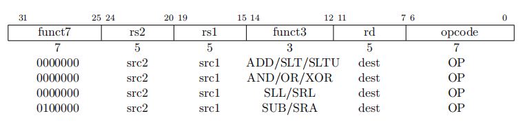
There are a total of 10 instructions in R-Type, with the opcode named OP and a value of 011_0011 (all R-Type instructions share the same opcode value).
1. ADD
The “ADD” instruction is an example of a RISC-V “R-type” instruction, where R stands for “register”. R-type instructions operate on two source registers and store the result in a destination register.
We have learned the operation principle of the ADDI instruction in the I-Type integer register-immediate instruction, which is similar to the ADD instruction but with the immediate value split into a funct7 field of 7 bits and an rs2 field of 5 bits.
The ADD instruction format
ADD rd, rs1, rs2, where x[rd] = x[rs1] + x[rs2].
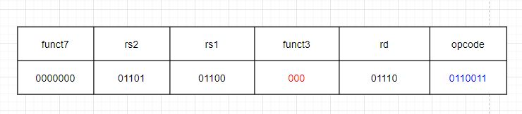
The funct7 field is 000_0000 and the funct3 field is 000.This instruction adds the values in registers rs1 and rs2 and writes the result to rd.

Note that this is not the addition of bit 15-19 and bit 20-24 of the machine code, but the addition of the values in the registers corresponding to their index numbers.
Similar to ADDI, any overflow is ignored, and only the lower XLEN bits are written to rd.
An example of overflow in addition is given, where adding two 8-bit signed binary numbers 0100_0000 (64) and 0111_0000 (112) results in 1011_0000 (-80), which is obviously incorrect.
1.1 Example
ADD x14,x12,x13
Add the numbers in registers x12 and x13 and store the result in register x14.
- OP-IMM: 011_0011
- funct3: 000
- funct7: 7’b000_0000
- rs2: 5’b0_1101
- rs1: 5’b0_1100
- rd: 5’b0_1110
ADD x14,x12,x13
machines code is: 0000000_01101_01100_000_01110_0110011 (32’ h00d6_0733)
2. SLT
Set Less Than
It compares two signed source integers, and sets the destination register to 1 if the first integer is less than the second integer, or 0 otherwise.
Format Instruction:
SLT rd,rs1,rs2. x[rd] = x[rs1] <𝑠 x[rs2]

2.1 Example
SLT x14,x12,x13
Compare the numbers in registers x12 and x13 as signed integers. If the number in x12 is less than the number in x13, set the number in x14 register to 1, otherwise set it to 0.
The SLT instruction does not perform an actual subtraction operation between the two integers. Instead, it performs a comparison of the sign bits and magnitude of the integers to determine the result.
If either rs1 or rs2 contains an unsigned value, then the comparison is performed as if the unsigned value were signed. This can lead to unexpected results if the unsigned value has the sign bit set.
SLT can be useful in programming situations where we need to compare two signed integers and make a decision based on the result of the comparison.
3. SLTU
Set Less Than Unsigned
Instruction Format:
SLTU rd,rs1,rs2. x[rd] = x[rs1] <𝑢 x[rs2]

Compare the numbers in the x12 and x13 registers as unsigned numbers. If the number in the x12 register is less than the number in the x13 register, set the x14 register to 1, otherwise set it to 0.
4. AND
AND (&)
Instruction Format:
AND rd,rs1,rs2. x[rd] = x[rs1] & x[rs2]

As shown in Figure 5, the funct7 of the AND instruction is 000_0000, and the funct3 is 111. This instruction writes the result of rs1 & rs2 into rd, where “&” means bitwise AND between rs1 and rs2.
4.1 Example
AND x14,x12,x13
Write the result of bitwise AND between the numbers in the x12 and x13 registers into the x14 register.
5. OR
OR ( | )
Instruction Format:
OR rd,rs1,rs2. x[rd] = x[rs1] | x[rs2]

As shown in Figure 6, the funct7 of the OR instruction is 000_0000, and the funct3 is 110. This instruction writes the result of rs1 | rs2 into rd, where “|” means bitwise OR between rs1 and rs2.
5.1 Example
OR x14,x12,x13
Write the result of bitwise OR between the numbers in the x12 and x13 registers into the x14 register.
6. XOR
XOR ( ^ )
Instruction Format:
XOR rd,rs1,rs2. x[rd] = x[rs1] ^ x[rs2]
As shown in Figure 7, the funct7 of the XOR instruction is 000_0000, and the funct3 is 100. This instruction writes the result of rs1 XOR rs2 into rd, where “XOR” means bitwise exclusive OR between rs1 and rs2.

6.1 Example
XOR x14,x12,x13
Write the result of bitwise XOR between the numbers in the x12 and x13 registers into the x14 register.
7. SLL
Shift Left Logical
Instruction Format:
SLL rd,rs1,rs2. x[rd] = x[rs1] ≪ x[rs2]
As shown in Figure 8, the funct7 of the SLL instruction is 000_0000, and the funct3 is 001. This instruction left shifts rs1 by the number of bits specified by rs2 (the value in this register), filling the vacated positions with 0, and writes the result into the rd register. The lower 5 bits of the rs2 register represent the number of bits to be shifted (up to a maximum of 2^5 – 1 = 31), and its higher bits are ignored.

7.1 Example
SLL x14,x12,x13
Left shift the value in x12 by the number of bits specified by the lower 5 bits (higher bits are ignored) of the number stored in the x13 register, filling the vacated positions with 0, and write the result into the x14 register.
8. SRL
Shift Right Logical
Instruction Format:
SRL rd,rs1,rs2. x[rd] = x[rs1] ≫𝑢 x[rs2]

As shown in Figure 9, the funct7 of the SRL instruction is 000_0000, and the funct3 is 101. This instruction right shifts rs1 by the number of bits specified by rs2 (the value in this register), filling the vacated positions with 0, and writes the result into the rd register. The lower 5 bits of the rs2 register represent the number of bits to be shifted (up to a maximum of 2^5 – 1 = 31), and its higher bits are ignored.
8.1 Example
SRL x14,x12,x13
Right shift the value in x12 by the number of bits specified by the lower 5 bits (higher bits are ignored) of the number stored in the x13 register, filling the vacated positions with 0, and write the result into the x14 register.
9. SRA
Shift Right Arithmetic
Instruction Format:
SRA rd,rs1,rs2

As shown in Figure 10, the funct7 of the SRA instruction is 010_0000, and the funct3 is 101. This instruction right shifts rs1 by the number of bits specified by rs2 (the value in this register), filling the vacated positions with the value of the most significant bit (rs1[31]) of the rs1 register, and writes the result into the rd register. The lower 5 bits of the rs2 register represent the number of bits to be shifted (up to a maximum of 2^5 – 1 = 31), and its higher bits are ignored.
9.1 Example
SRA x14,x12,x13
Shift the value in x12 register to the right by the number of bits specified by the lower 5 bits of the x13 register (ignoring the higher bits), fill the vacated positions with the value of the most significant bit (sign bit) of the value stored in x12 register, and write the result into the x14 register.
Note:
In the three shift instructions mentioned above, the value in the rs1 register is only copied, and the original value remains unchanged.
10. SUB
SUBtract
Instruction Format:
SUB rd,rs1,rs2. x[rd] = x[rs1] − x[rs2]
The SUB instruction shown in Figure 11 has a funct7 of 010_0000 and funct3 of 000. This instruction subtracts the value in the rs2 register from the value in the rs1 register, ignoring arithmetic overflow.

10.1 Example
SUB x14,x12,x13
Subtract the value stored in register x13 from the value stored in register x12, and write the result to register x14 (ignoring arithmetic overflow).