1.Analog Signals and Digital Signals
Analog signals: Signals that are continuous in time and value are called analog signals, as shown in Figure 1:
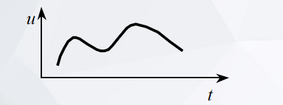
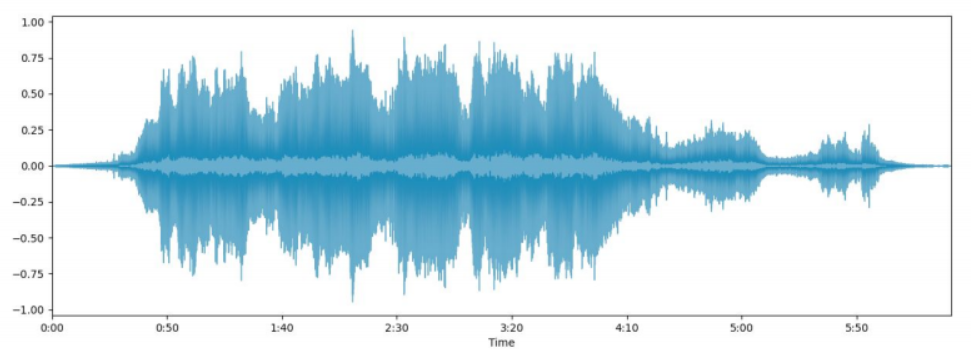
Figure 1 shows the waveform of a voltage signal, where the amplitude u varies with time t. The time t is continuous, and the variation of the voltage u is also continuous. Continuous signals are ubiquitous in nature, such as speech signals, temperature signals, and current signals, among others. A typical speech signal is shown in Figure 2.
Analog signals are also known as analogue signals. “analog signal” and “analogue signal” are used interchangeably to refer to a signal that is continuous in time and value. The term “analog” is more commonly used in North America, while “analogue” is more commonly used in Europe and other regions. Both terms are widely understood in the field of electronics and signal processing.
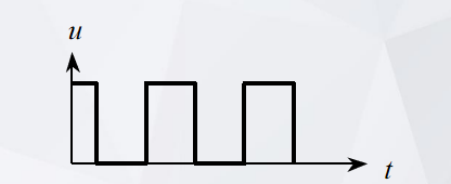
2. Digital Signal
A digital signal is a signal that is discrete in both time and amplitude. Unlike analog signals, which are continuous, digital signals are composed of a finite number of discrete values or levels, usually expressed as binary code (0s and 1s). Figure 3 shows an example of a digital signal, where both the time and amplitude are discrete.
2.1. A discrete signal
A discrete signal, also known as a discrete-time signal, is a signal that is discrete in time but continuous in amplitude. Figure 4 and Figure 5 show examples of discrete signals where the time is discrete and the amplitude is continuous.
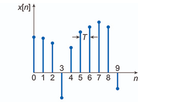
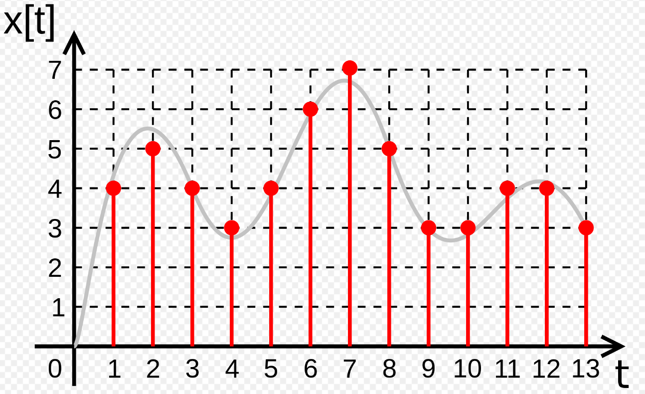
The signal shown in Figure 5 is a discrete signal obtained by sampling a continuous signal. Each point in the figure corresponds to a specific moment in time. This type of sampling is generally referred to as ideal sampling. Ideal sampling is only a mathematical model and cannot be achieved by actual samplers.
2.2 Non-ideal Sampling Signal
Non-ideal sampling is shown in Figure 6.
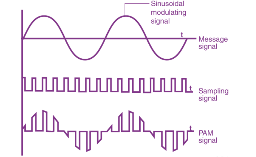
Figure 6 is a non-ideal sampling signal, also known as pulse amplitude signal or pulse amplitude modulation.
The non-ideal pulse sampling signal refers to the distortion or distortion of the sampled signal due to the inability of the sampler to sample in accordance with the ideal sampling method during pulse sampling. These non-ideal factors may include noise in the sampler itself, clock jitter, inconsistent sampling intervals, and so on. These factors may affect the sampled signal and thus affect the results of signal processing.
Therefore, in practical applications, it is necessary to have a full understanding and analysis of non-ideal sampling and to take corresponding compensation and correction measures to ensure the accuracy and reliability of the sampled signal.
3.The Process of Converting an Analog Signal to a Digital Signal
The process of converting an analog signal to a digital signal is called analog-to-digital conversion (ADC). The implementation of converting an analog signal to a digital signal usually involves three steps, as shown in Figure 7:
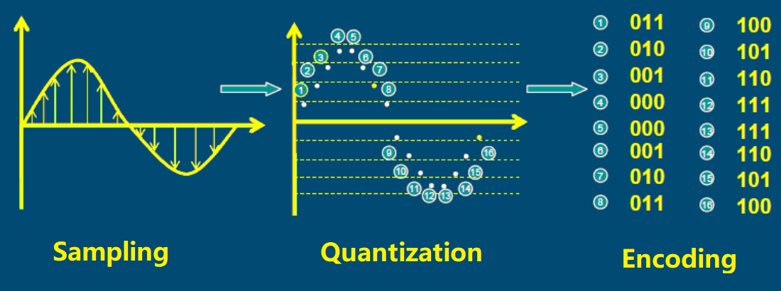
- Sampling: Sample the analog signal at a certain time interval to obtain a series of sample values, which converts the continuous-time signal into a discrete-time signal.
- Quantization: Convert each sample value into a digital value with a certain number of levels, which is a discrete amplitude signal representing the analog signal’s amplitude.
- Encoding: Convert the quantized discrete-amplitude signal into a digital signal, which is a binary code. Encoding is the process of encoding the discrete amplitude signal. There are various ways to encode, but the most widely used is two’s complement binary code, as shown in Figure 7. The signal after encoding is generally called Pulse Code Modulation (PCM) encoding, which is a digital signal. Knowledge related to encoding will be introduced in courses such as communications and coding.
These three steps are the basic steps for converting analog signals into digital signals, and there are various ways to implement them. For example, according to the different sampling methods, they can be divided into sample-and-hold sampling and pulse-code modulation (PCM) sampling. According to the different quantization methods, they can be divided into linear quantization and nonlinear quantization, and so on.
Once the digital signal is obtained successfully, it can be processed through digital signal processing. Generally, in the process of analog-to-digital or digital-to-analog conversion, A/D (analog-to-digital converter) and D/A (digital-to-analog converter) devices are commonly used. The principles and applications of A/D and D/A converters will be discussed in detail in subsequent chapters.