This article will start with the I-Type integer register instructions and provide a detailed introduction to each assembly instruction and its specific implementation.
I-type Integer Register-Immediate Instructions
I-Type – Immediate Type.
Apart from the CSR (Control and Status Register) instructions, all immediate values that appear are sign-extended and usually placed in the most significant bits (leftmost bit) that are available in the instruction.
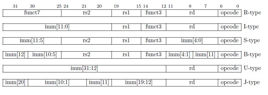
All instruction types (I-type, S-type, B-type, U-type, and J-type) that use immediate values have their sign extension determined by bit 31 of the instruction (which is also the highest bit of the immediate value, such as imm[20] in J-type instructions).
Therefore, the immediate values mentioned in I-type instructions are all sign-extended.
Here is an example to explain sign extension. For instance, consider a 12-bit immediate value.
If the highest bit is 0, the immediate value is positive. If the highest bit is 1, the immediate value is negative. When sign-extending a positive immediate value, the upper 20 bits are filled with 0s. When sign-extending a negative immediate value, the upper 20 bits are filled with 1s. After sign extension, the immediate value can be added or compared with other operands.
On the other hand, when performing unsigned extension, the upper 20 bits are filled with 0s regardless of whether the immediate value is positive or negative.
For example, if the value of a signed 12-bit immediate is 0xF8C (i.e., the binary number 1111 1000 1100), it is a negative number with a sign bit of 1. When performing sign extension, we fill all the remaining bits with 1s, resulting in 0xFFFFF8C. This result is a 32-bit binary number that represents the sign-extended value of the signed immediate value.
Most integer arithmetic instructions operate on the XLEN bits stored in integer registers (corresponding to 32 bits in RV32I). Integer arithmetic instructions either use I-type instructions for register-immediate operations or use R-type instructions for register-register operations.
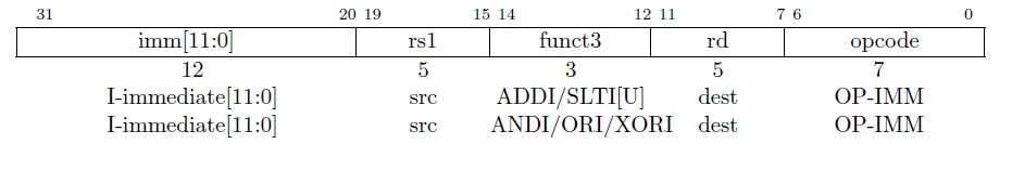
The opcode corresponding to I-type is named OP-IMM.
The immediate value corresponding to I-type instructions is fixed at 12 bits and is named I-immediate, as shown in Figure 2.
There are a total of 15 instructions in I-type category. We will introduce the first six instructions, which are:
- ADDI
- SLTI
- SLTIU
- ANDI
- ORI
- XORI
1.1. ADDI
ADD Immediate
The ADDI instruction format :
ADDI rd, rs1, immediate.
x[rd] = x[rs1] + sext(imm).
For example:
ADDI x13, x12, 5
This instruction adds the value in the x12 register to the sign-extended immediate value of 5, and stores the result in the x13 register.

- OP-IMM (0-6) : 001_0011
- funct3 (12-14) : 000
- immediate (20-31): 12’ b0000_0000_0101
- rs1 (15-19): 5’b0_1100
- rd (7-11): 5’b0_1101
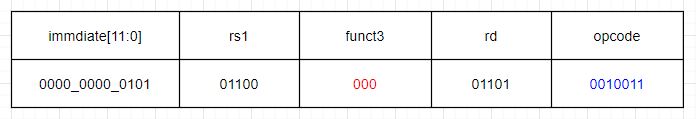
ADDI x13,x12,5 machine code format:
0000_0000_0101_01100_000_01101_0010011
The corresponding hexadecimal value is 32’h0056_0693.
After decoding, if the opcode and funct3 fields of the machine code correspond to 001_0011 and 000, then the instruction is definitely an ADDI instruction. In ADDI, “ADD” stands for addition, “I” stands for immediate, and the full name of ADDI is immediate addition. This instruction adds the value in the rs1 register to the sign-extended immediate value, and stores the result in the rd register (ignoring any overflow. Overflow handling can be implemented by software).
Here, we need to introduce a concept called “pseudo-instruction”. A pseudo-instruction is an instruction that does not exist in the assembly instruction set. These instructions are convenient for assembly language programmers and are often used.
1.1.1 Pseudo-Instruction
A pseudo-instruction is a symbolic representation of one or more actual machine instructions. It is not a real instruction that is executed by the CPU, but rather a convenient notation used in assembly language programming to make the code more readable and easier to write. Pseudo-instructions are typically used to represent complex or frequently used sequences of instructions that can be more easily written using a shorthand notation. During the assembly process, the pseudo-instructions are translated into one or more actual machine instructions that can be executed by the CPU.
Pseudo-Instruction Example 1: in assembly programs, it is common to move data between registers, which is why the pseudo-instruction MV (move) exists.
- Instruction format: MV rd, rs1.
- This instruction moves the value in the rs1 register to the rd register (the x86 has a move instruction and the MCS-51 also has this instruction). In fact, it actually represents the meaning of ADDI rd, rs1, 0, which means adding the value in the rs1 register to the immediate value 0, and then storing the result in the rd register.Because adding 0 to rs1 does not change the value of rs1, the MV instruction actually moves the value of rs1 to rd.
- When writing assembly programs, users can write such a pseudo-instruction MV. During program compilation, the compilation software will translate this instruction into ADDI rd, rs1, 0, and then send this ADDI instruction to the CPU for execution.
Pseudo-Instruction Example 2: There is another frequently used pseudo-instruction called NOP (no operation).
- Instruction format: NOP.
- The actual meaning of NOP is ADDI x0, x0, 0. As mentioned before, the value of x0 cannot be changed, only read, and is always 0. Therefore, ADDI x0, x0, 0 performs an addition with no result, and puts the result of x0 + 0 into x0. Its only purpose is to push forward the value of the PC.
1.2. SLTI
Set if Less Than Immediate
The SLTI instruction format :
SLTI rd,rs1,immediate。
x[rd] = x[rs1] <𝑠 sext(immediate)
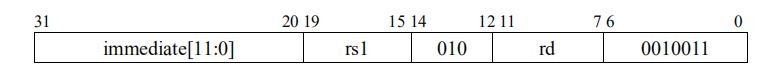
The machine code for SLTI is shown in figure 4, where the OP-IMM field is 001_0011 and funct3 is 010. In SLTI, the “S” stands for set, which means to set the value of rd to 0 or 1 after signed comparison of rs1 and the sign-extended immediate value. Note that the instruction sets the bit to 1 if the condition is true and 0 if it is false. The condition tested by this instruction is LT (less than), which means it checks if the value in rs1 is less than the immediate value. SLTI stands for set if less than immediate.
SLTI x13,x12,5
Compare the value in register x12 with the immediate value 5 (sign-extended to 5), and if the value in x12 is less than 5 (signed comparison), set x13 to 1.
1.3. SLTIU
Set if Less Than Immediate Unsigned
instruction format :
SLTIU rd,rs1,immediate . x[rd]= x[rs1] <𝑢 sext(immediate)
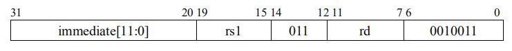
Its machine code is shown in Figure 5, with OP-IMM of 001_0011 and funct3 of 011 for the SLTIU instruction. The only difference between SLTIU and SLTI is that “U” stands for unsigned number, and the immediate value is sign-extended and treated as an unsigned number for comparison, with the result being written back to the register.
If we compare two 8-bit binary numbers, -1: 8’b1111_1111, and -2: 8’b1111_1110, when compared as signed numbers, -2 is less than -1. If compared as unsigned numbers, the comparison still holds. However, if we compare -2 and +1: 8’b0000_0001 as unsigned numbers, then 1111_1110 > 0000_0001, and 254 is greater than 1.
1.3.1 Example
SLTIU x13,x12,-1
To compare register x12 with immediate value -1 (sign-extended to 0xffffffff), and set x13 to 1 if the value in register x12 is less than 0xffffffff when treated as an unsigned number.
1.3.2 The Pseudo-Instruction SEQZ
The pseudo-instruction SEQZ (set if equal to zero) can be expressed as SEQZ rd, rs1, which is equivalent to the instruction SLTIU rd, rs1, 1. This pseudo-instruction is a special case of SLTIU and is commonly used. In unsigned numbers, there is only one case where rs1 is less than “1”, which is when rs1 equals 0.
Therefore, if the comparison SLTIU rd, rs1, 1 holds, it can also be considered that SEQZ rd, rs1 holds when rs1 equals 0.
1.4. ANDI
And Immediate
instruction format :
ANDI rd,rs1,immediate。x[rd] = x[rs1] & sext(immediate)

The machine code for the ANDI instruction is shown in Figure 6, with OP-IMM of 001_0011 and funct3 of 111. The ANDI instruction performs a bitwise AND operation between the sign-extended immediate value and the value in register rs1. The result is written back to the destination register rd.
1.4.1 Example
ANDI x13,x12,5
To perform a bitwise AND operation between the value in register x12 and the sign-extended immediate value 5, and store the result in register x13
1.5. ORI
OR Immedicate
instruction format :
ORI rd,rs1,immediate。x[rd] = x[rs1] | sext(immediate)

1.5.1 Example
ORI x13,x12,5
To perform a bitwise OR operation between the value in register x12 and the sign-extended immediate value 5, and store the result in register x13
1.6. XORI
XOR Immediate
instruction format :
XORI rd,rs1,immediate。x[rd] = x[rs1] ^ sext(immediate)

The machine code for the XORI instruction is shown in Figure 8, with OP-IMM of 001_0011 and funct3 of 100. The XORI instruction performs a bitwise XOR operation between the sign-extended immediate value and the value in register rs1. The result is written back to the destination register rd.
1.6.1 Pseudo-instruction NOT
Pseudo-instruction NOT: NOT rd, rs1 (equivalent to XORI rd, rs1, 12’hfff).
The NOT instruction performs a bitwise negation operation on the value in register rs1 and stores the result in register rd. This is achieved by XORing the sign-extended value of 12’hfff with the value in rs1. Since XORing 1 with any value performs a bitwise negation, XORing 12’hfff with rs1 achieves the same result.
1.6.2 example
XORI x13,x12,5
XOR the number in register x12 with the signed immediate number 5 after sign extension, and write the result to register x13.
RISC-V instructions are flexible. The machine code formats of the instructions above do not enforce a specific register for rs1 and rd. Users can choose the corresponding registers from the 32 general-purpose registers as needed when writing assembly programs, and rs1 and rd can even be the same register.