Introduction
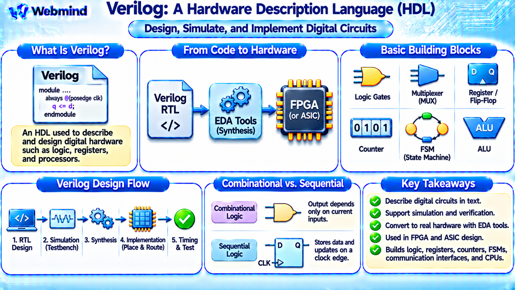
Verilog is a Hardware Description Language (HDL) used to describe, simulate, and design digital electronic circuits.
It is widely used in FPGA development, ASIC design, processor architecture, and semiconductor engineering.
Unlike conventional programming languages such as Python or C, which primarily describe instructions executed by a processor, Verilog describes the behavior and structure of digital hardware.
Engineers use Verilog to design logic gates, registers, counters, Finite State Machines (FSMs), memory controllers, and complete processor systems.
Verilog is one of the most important languages in digital hardware development, alongside VHDL and its successor, SystemVerilog.
How Does Verilog Work?
Verilog allows engineers to describe how digital circuits process signals and store information.
For example, a designer can use Verilog to describe an AND gate with two inputs and one output.
The statement:
assign y = a & b;
describes a bitwise AND operation between signals a and b.
If both signals are single bits, the output becomes 1 only when both inputs are 1.
Unlike ordinary sequential software execution, different hardware structures described in Verilog can operate concurrently.
This reflects the parallel nature of digital electronic circuits.
After writing Verilog, engineers use Electronic Design Automation (EDA) tools to simulate, synthesize, and implement the design.
What Is a Verilog Module?
A module is the basic building block of a Verilog design.
It describes a hardware component with inputs, outputs, and internal logic.
For example, a two-input AND gate can be described as:
module and_gate(input a, input b, output y);
assign y = a & b;
endmodule
The module has two inputs, a and b, and one output, y.
The assignment statement describes the logical relationship between the signals.
Larger Verilog designs can contain many interconnected modules.
For example, a processor may include separate modules for its ALU, register file, control unit, and memory interfaces.
Combinational Logic in Verilog
Combinational logic produces outputs based on current input values without storing previous states.
Examples include AND gates, OR gates, multiplexers, decoders, and arithmetic circuits.
A simple two-input multiplexer can be described using:
assign y = s ? d1 : d0;
Here, s is the select signal.
When s is 0, the output follows d0. When s is 1, the output follows d1.
Verilog also supports procedural descriptions using always blocks.
For example, always @(*) can be used to describe combinational logic using conditional statements.
Designers must ensure that intended combinational outputs receive assignments in every relevant execution path to avoid unintended latch inference.
Sequential Logic in Verilog
Sequential logic stores information and changes state according to clock events or other control signals.
Examples include registers, counters, flip-flops, and state machines.
A simple D flip-flop can be described using:
always @(posedge clk) q <= d;
The statement means that q captures the value of d at each rising clock edge.
The symbol <= is the nonblocking assignment operator, commonly used in clocked sequential logic.
Nonblocking assignments help model the behavior of registers that update together at a clock event.
Sequential logic is essential for implementing state storage and synchronous digital systems.
What Is the Difference Between Blocking and Nonblocking Assignments?
Verilog provides two important procedural assignment operators.
Blocking Assignment (=): Updates a procedural variable immediately within the current procedural execution sequence.
Nonblocking Assignment (<=): Schedules an update for a later simulation event region, allowing multiple sequential elements to model concurrent clocked updates.
Blocking assignments are commonly used in combinational procedural logic.
Nonblocking assignments are generally preferred for clocked sequential logic.
For example, using nonblocking assignments in a register pipeline helps ensure that each stage captures the previous value of the preceding stage.
Using these operators incorrectly can cause simulation behavior that differs from the designer’s intention.
What Are Wires and Registers in Verilog?
Traditional Verilog uses data types such as wire and reg.
wire: Represents a net whose value is driven by continuous assignments or connected module outputs.
reg: Represents a procedural variable that retains its assigned value until another procedural assignment changes it.
Despite its name, reg does not automatically mean that a physical hardware register will be created.
A reg variable assigned in a combinational process may be synthesized into combinational logic.
A reg variable assigned in an edge-triggered process may be synthesized into flip-flops.
SystemVerilog introduced improved data types, including logic, that simplify many signal declarations.
Understanding the difference between Verilog language variables and physical storage elements is important for hardware design.
How Do You Build a Counter in Verilog?
A counter is a common beginner project in FPGA development.
A binary counter stores a numerical value and increments it in response to a clock.
For example:
always @(posedge clk) count <= count + 1'b1;
This statement describes a counter that increments at each rising clock edge.
If count is an unsigned four-bit variable, its value cycles from 0000 through 1111 and then returns to 0000.
Practical counter designs usually include reset and enable signals.
During synthesis, the counter is implemented using flip-flops and arithmetic logic.
On an FPGA, the arithmetic may use dedicated carry-chain resources.
What Is a Verilog Testbench?
A testbench is a simulation environment used to verify a hardware design before implementing it.
It generates input signals, controls simulation timing, and checks output behavior.
For example, a testbench for an AND gate may apply the four possible combinations of two binary inputs.
It then checks whether the output matches the expected truth table.
Testbenches can also verify more complex circuits, including counters, state machines, and communication controllers.
Simulation is particularly useful because hardware errors can be identified before programming an FPGA or manufacturing an ASIC.
Testbench code may contain simulation-only features that cannot be synthesized into physical hardware.
What Is Verilog Simulation?
Verilog simulation evaluates the behavior of a digital hardware description over simulated time.
A simulator processes signal changes and executes the relevant Verilog statements according to the language’s event-scheduling rules.
For example, a designer can simulate a counter and observe how its outputs change at each clock edge.
Simulation tools can display waveforms showing clock signals, data inputs, and outputs.
Common Verilog simulation tools include Icarus Verilog, Verilator, and commercial EDA simulators.
Simulation helps verify functional correctness, but RTL simulation alone does not guarantee that the implemented hardware will satisfy physical timing requirements.
What Is Verilog Synthesis?
Synthesis is the process of converting a synthesizable Verilog description into a hardware implementation.
For FPGA development, synthesis maps logic into resources such as LUTs, flip-flops, Block RAM, and DSP blocks.
For ASIC development, synthesis maps the design into a network of standard cells from a semiconductor technology library.
For example, a Verilog addition expression may be converted into an adder circuit.
A clocked assignment may become a register.
However, not every Verilog statement can be synthesized.
Simulation delays, arbitrary file operations, and many testbench constructs do not directly represent hardware structures.
Designers must distinguish between synthesizable RTL and simulation-only code.
Verilog in FPGA Development
Verilog is widely used to design programmable digital hardware.
A typical FPGA development process includes several stages.
RTL Design: Describe the required hardware using Verilog.
Simulation: Verify circuit functionality using testbenches.
Synthesis: Convert the RTL into FPGA-compatible logic resources.
Placement and Routing: Assign the hardware resources to physical locations and connect them.
Timing Analysis: Check setup time, hold time, and clock-frequency requirements.
Bitstream Generation: Produce the configuration data for the FPGA.
Hardware Testing: Program the FPGA and verify its operation.
Popular FPGA development tools include AMD Vivado and Intel Quartus Prime.
Verilog in ASIC Development
Verilog is also an important language in ASIC design.
Engineers describe the required digital circuits using RTL.
EDA tools then synthesize the design into standard-cell logic.
Physical implementation tools perform floorplanning, placement, clock-tree synthesis, and routing.
Static Timing Analysis verifies whether the circuit satisfies timing constraints.
Physical verification checks whether the layout follows the manufacturing rules of the selected semiconductor process.
After verification, the completed design is prepared for tape-out and manufacturing.
Unlike FPGA implementation, an ASIC design usually cannot be reconfigured after fabrication.
What Is SystemVerilog?
SystemVerilog is an extension and evolution of Verilog.
It adds features for both hardware design and verification.
Important SystemVerilog capabilities include improved data types, interfaces, enumerated types, assertions, and specialized procedural blocks.
For example, always_comb is commonly used for combinational logic, while always_ff is used for sequential logic.
SystemVerilog also provides advanced verification features such as classes, constrained random testing, and functional coverage.
The IEEE 1800 standard defines SystemVerilog, including the Verilog language features incorporated into it.
Modern semiconductor development frequently uses SystemVerilog for RTL design and verification.
Verilog vs. VHDL
Verilog and VHDL are two major Hardware Description Languages.
Both can describe combinational logic, sequential circuits, and complete digital systems.
Verilog: Uses syntax influenced by C-like programming languages and is widely used in FPGA and ASIC development.
VHDL: Uses a strongly typed language structure and is also widely used in industrial, aerospace, and FPGA applications.
Both languages support simulation and synthesis.
Neither language is inherently faster in hardware. The resulting performance depends on the synthesized circuit, target technology, constraints, and implementation tools.
The choice often depends on engineering requirements, existing codebases, tool support, and team preferences.
Verilog vs. C and Python
Verilog differs fundamentally from conventional programming languages.
C and Python primarily describe software executed by a processor or interpreter.
Verilog describes hardware structures and concurrent signal behavior.
For example, a loop in Python normally executes instructions according to software execution rules.
A loop in synthesizable Verilog may describe repeated hardware structures or logic operations, depending on how it is written.
This distinction is important because FPGA hardware is not simply a CPU executing Verilog instructions.
Instead, Verilog is used to describe circuits that are implemented in configurable hardware.
What Can You Build with Verilog?
Verilog supports a wide range of digital hardware projects.
Logic Gates: AND, OR, NOT, XOR, NAND, and other Boolean functions.
Multiplexers and Decoders: Data selection and control logic.
Registers and Counters: Sequential storage and event counting.
Finite State Machines: Controllers that operate through defined states.
Communication Interfaces: UART, SPI, I2C, and custom protocols.
Arithmetic Circuits: Adders, comparators, multipliers, and ALUs.
Memory Controllers: Logic for coordinating memory access.
Processor Cores: Custom CPUs and other programmable processing architectures.
These projects range from simple introductory exercises to complex commercial semiconductor designs.
Can You Learn Verilog Without an FPGA Board?
Yes. Verilog can be learned and practiced without purchasing an FPGA development board.
A beginner can write simple hardware modules and simulate them using software tools.
For example, a student can design an AND gate, create a testbench, and verify its truth table.
The next step may be implementing a counter or finite state machine.
Open-source tools such as Icarus Verilog, Verilator, GTKWave, and Yosys can support different parts of the learning process.
Online HDL simulation environments are also available.
After understanding basic simulation and RTL design, a student can move to FPGA synthesis and physical hardware testing.
This approach allows beginners to learn digital design concepts before investing in development hardware.
Why Is Verilog Important?
Verilog connects digital logic theory with practical hardware engineering.
It allows engineers to describe complex circuits using structured text instead of manually drawing every gate and connection.
It also supports simulation, verification, synthesis, and automated implementation.
Modern CPUs, GPUs, memory controllers, communication chips, and specialized accelerators all depend on hardware design methodologies that use HDLs such as Verilog and SystemVerilog.
For FPGA development, Verilog provides a practical way to turn Boolean functions, counters, and state machines into working digital hardware.
Conclusion
Verilog is a Hardware Description Language used to design, simulate, and implement digital electronic circuits.
Unlike conventional software programming languages, Verilog describes hardware behavior and structure, including concurrent combinational and sequential operations.
It is widely used in FPGA development, ASIC design, processor architecture, and semiconductor engineering.
Important concepts include modules, combinational logic, sequential logic, testbenches, simulation, synthesis, and timing analysis.
Understanding Verilog provides an essential foundation for studying FPGA architecture, ASIC development, Boolean algebra, digital circuit design, SystemVerilog, and modern computer engineering.