Introduction
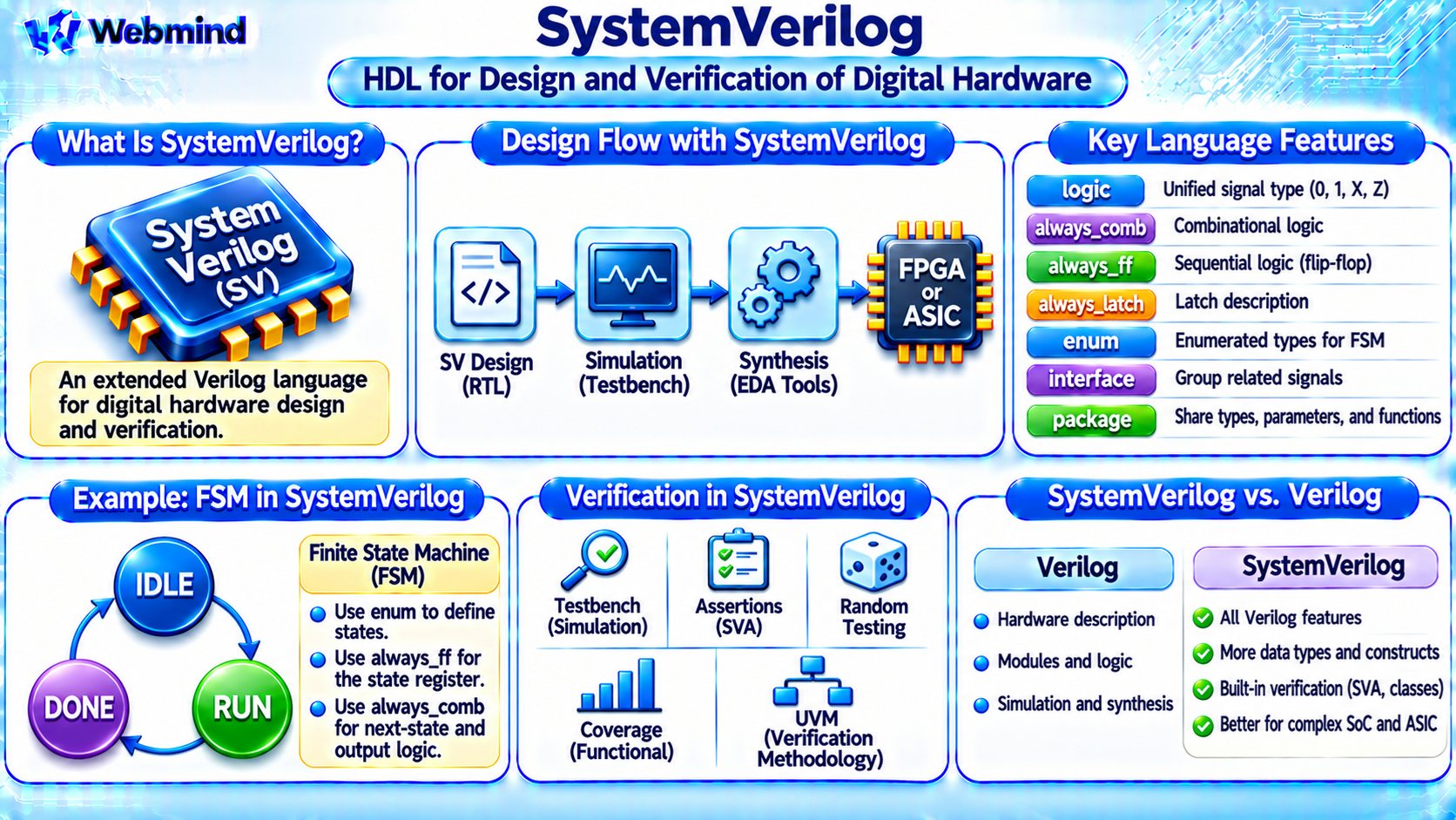
SystemVerilog is a Hardware Description and Verification Language (HDVL) used to design, simulate, and verify digital electronic circuits.
It extends the Verilog hardware description language with additional features for hardware design, functional verification, and complex semiconductor development.
SystemVerilog is widely used in FPGA development, ASIC design, CPU and GPU engineering, System-on-Chip (SoC) development, and semiconductor verification.
Unlike conventional software programming languages such as C or Python, SystemVerilog can describe hardware structures that operate concurrently.
It also includes programming features that help engineers build sophisticated simulation environments.
SystemVerilog is standardized under IEEE 1800 and has become one of the most important languages in modern digital hardware engineering.
SystemVerilog vs. Verilog: What Is the Difference?
SystemVerilog is an extension of Verilog rather than a completely unrelated language.
Traditional Verilog provides constructs for describing digital logic, modules, signals, registers, and clocked circuits.
SystemVerilog adds improved data types, more expressive hardware design constructs, interfaces, assertions, object-oriented programming, and advanced verification capabilities.
Verilog: Primarily provides hardware description and simulation features for digital circuits.
SystemVerilog: Supports hardware design while also providing a comprehensive language for functional verification.
Most conventional Verilog designs can be used within SystemVerilog environments, although compatibility details depend on the source code and tools.
SystemVerilog is commonly preferred for new digital design and verification projects.
How Does SystemVerilog Work?
SystemVerilog allows engineers to describe both combinational and sequential digital circuits.
For example, a designer can describe an AND gate, multiplexer, counter, register, or Finite State Machine (FSM).
The hardware description is processed by Electronic Design Automation (EDA) tools.
Simulation tools evaluate the design’s behavior, while synthesis tools translate supported SystemVerilog constructs into digital hardware.
For FPGA development, synthesis can map a design onto Look-Up Tables (LUTs), flip-flops, Block RAM, DSP blocks, and other programmable resources.
For ASIC development, synthesis produces a logic implementation using semiconductor standard cells.
SystemVerilog also supports verification code that tests the design without becoming part of the manufactured hardware.
What Is the Logic Data Type?
One important SystemVerilog feature is the logic data type.
Traditional Verilog commonly uses wire for nets and reg for procedural variables.
SystemVerilog introduces logic as a convenient four-state variable type for many digital signals.
The four simulation values are:
0: Logical zero.
1: Logical one.
X: Unknown value.
Z: High-impedance value.
For example:
logic [7:0] data;
This declares an eight-bit signal named data.
The logic type can be used for many combinational and sequential signal declarations.
However, it does not automatically create a physical register. The resulting hardware depends on how the signal is assigned.
SystemVerilog also retains net types such as wire for signals requiring net-resolution behavior.
Combinational Logic with always_comb
SystemVerilog introduces always_comb to describe combinational logic.
For example:
always_comb y = a & b;
This describes a combinational AND function.
Unlike traditional Verilog’s always @(*), always_comb provides additional semantic checks and automatically handles sensitivity to signals read by the process.
Designers can also use conditional statements and case statements inside combinational blocks.
All outputs should be assigned for every possible control path when combinational hardware is intended.
Otherwise, incomplete assignments may imply storage behavior or produce tool warnings.
Sequential Logic with always_ff
SystemVerilog provides always_ff for describing sequential logic.
For example:
always_ff @(posedge clk) q <= d;
This describes a positive-edge-triggered D flip-flop.
At each rising clock edge, q captures the value of d.
The nonblocking assignment operator <= is generally used for clocked sequential logic.
The always_ff construct also allows tools to perform additional checks on how sequential variables are assigned.
SystemVerilog makes the designer’s intention clearer by distinguishing combinational logic from clocked storage.
What Is always_latch?
SystemVerilog includes always_latch for describing level-sensitive storage elements.
A latch stores information while an enable condition is inactive and may follow its input while enabled.
For example:
always_latch if (en) q <= d;
This describes an active-high D latch.
When en is 1, q follows d. When en is 0, q retains its previous value.
The always_latch construct explicitly indicates that latch behavior is intended.
This is useful because unintended latches can introduce timing problems in FPGA and ASIC designs.
For ordinary synchronous digital systems, designers commonly use flip-flops unless level-sensitive storage is specifically required.
What Are Enumerated Types?
SystemVerilog supports enumerated data types using the enum keyword.
Enumerated types allow engineers to assign meaningful names to numerical values.
They are especially useful for Finite State Machines.
For example:
typedef enum logic [1:0] {IDLE, RUN, DONE} state_t;
This creates a state type containing three named values.
A state variable can then be declared as:
state_t state;
Using meaningful state names makes hardware descriptions easier to read and maintain.
Enumerated types can also help simulation and verification tools identify invalid or unexpected states.
SystemVerilog and Finite State Machines
Finite State Machines are widely used in digital control circuits.
An FSM contains a state register, next-state logic, and output logic.
SystemVerilog provides convenient constructs for describing these components.
For example, an FSM can use always_ff to update its current state and always_comb to calculate the next state.
An enumerated type can define states such as IDLE, WAIT, PROCESS, and DONE.
This organization separates sequential storage from combinational decision-making.
FSMs are commonly used in communication interfaces, processor controllers, robotics, and FPGA-based embedded systems.
What Is a SystemVerilog Interface?
An interface groups related signals into a single reusable connection structure.
For example, a communication interface may contain address, data, valid, ready, and control signals.
Without an interface, these signals must often be connected individually between modules.
SystemVerilog interfaces allow related signals to be organized and passed together.
The language also provides modport declarations that define how different modules access interface signals.
Interfaces can improve readability and reduce connection errors in large digital designs.
However, synthesis support for interface features varies among EDA tools and target technologies.
What Are Packages in SystemVerilog?
A package provides a way to organize declarations shared by multiple modules and verification components.
A package may contain data types, parameters, constants, functions, and classes.
For example, a processor project may define common instruction types or configuration parameters inside a package.
Other design modules can import these definitions.
Packages help maintain consistency across complex hardware projects.
They are particularly valuable in large FPGA and ASIC designs involving many modules and engineers.
What Is Functional Verification?
Functional verification checks whether a digital design behaves according to its specification.
A circuit may compile and synthesize successfully but still contain logical errors.
SystemVerilog includes features that support advanced verification methods.
These include testbenches, assertions, constrained random stimulus, classes, coverage, and transaction-based verification.
For example, a verification environment may generate many combinations of input transactions and check whether a processor or communication controller produces the correct results.
This helps engineers identify problems before FPGA deployment or ASIC manufacturing.
Functional verification is a major part of modern semiconductor development.
What Is a SystemVerilog Testbench?
A testbench is a simulation environment used to test a hardware design, often called the Design Under Test (DUT).
The testbench generates input signals, observes outputs, and compares the results with expected behavior.
For example, a testbench for a counter can generate clock pulses, activate reset, and verify that the count increments correctly.
SystemVerilog testbenches can also use classes, randomized transactions, queues, and other programming features.
These advanced constructs make it possible to test complicated hardware systems.
However, most class-based verification code is intended for simulation rather than synthesis.
What Are SystemVerilog Assertions?
SystemVerilog Assertions (SVA) allow engineers to describe properties that a digital design must satisfy.
For example, a protocol may require that a request remain active until the receiving device acknowledges it.
An assertion can check this requirement during simulation or formal verification.
Assertions can detect violations involving signal timing, control sequences, and state transitions.
They are useful because they express expected behavior separately from the RTL implementation.
SVA supports immediate assertions and concurrent assertions.
Concurrent assertions are particularly valuable for checking behavior across multiple clock cycles.
What Is Constrained Random Verification?
Constrained random verification automatically generates test inputs within specified rules.
For example, a memory-controller testbench may generate random addresses, transaction sizes, and read/write operations.
Constraints ensure that generated transactions satisfy selected legal conditions.
The verification environment then checks whether the design handles these transactions correctly.
This technique helps explore combinations that engineers might overlook when writing tests manually.
However, random testing does not guarantee complete verification.
It is commonly combined with directed tests, assertions, coverage analysis, and other verification methods.
What Is Functional Coverage?
Functional coverage measures whether important design scenarios have been exercised during verification.
For example, a processor verification environment may track whether all required instruction types have been tested.
A communication controller may track packet sizes, command types, and error conditions.
SystemVerilog provides coverage constructs such as covergroups, coverpoints, and cross coverage.
Coverage reports help engineers identify missing test scenarios.
Functional coverage differs from code coverage, which measures whether parts of the source code have been exercised.
Both can provide useful information about verification progress.
What Is UVM?
UVM stands for Universal Verification Methodology.
It is a standardized methodology built primarily using SystemVerilog classes and verification features.
UVM provides reusable structures for building complex verification environments.
Typical UVM components include drivers, monitors, sequencers, agents, scoreboards, and test environments.
For example, a UVM testbench may generate transactions, send them to an interface, observe the resulting behavior, and compare outputs against a reference model.
UVM is widely used in professional ASIC and SoC verification.
However, beginners generally do not need UVM when learning basic digital logic or introductory FPGA design.
Understanding modules, simulation, testbenches, and assertions is a more practical starting point.
SystemVerilog in FPGA Development
SystemVerilog is widely used to develop FPGA hardware.
A typical workflow includes RTL design, simulation, synthesis, implementation, timing analysis, and hardware testing.
For example, a designer may describe a counter or UART controller using SystemVerilog.
Simulation verifies the expected behavior.
Synthesis converts the RTL into FPGA-compatible resources.
Placement and routing tools connect the hardware resources, and timing analysis checks whether the design meets the required clock constraints.
The resulting bitstream configures the FPGA.
FPGA tool support for SystemVerilog features varies, so designers must distinguish synthesizable constructs from simulation-only verification features.
SystemVerilog in ASIC Development
ASIC development uses SystemVerilog extensively for RTL design and functional verification.
Engineers describe processor cores, memory controllers, communication interfaces, and other digital circuits.
Verification teams build simulation environments to test complex hardware behavior.
Synthesis tools convert supported RTL into standard-cell logic.
Physical design tools then perform placement, routing, clock-tree synthesis, and timing optimization.
The completed layout undergoes physical verification before tape-out.
Because ASIC manufacturing is expensive, detecting design problems before fabrication is especially important.
SystemVerilog helps support this verification process.
SystemVerilog vs. VHDL
SystemVerilog and VHDL are both used in digital hardware engineering.
SystemVerilog: Combines RTL design with extensive verification features, including assertions, classes, and constrained random testing.
VHDL: Provides a strongly typed hardware description language with capabilities for modeling, simulation, synthesis, and verification.
Both languages can describe complex digital circuits.
The choice often depends on engineering requirements, existing projects, team experience, and EDA tool support.
Neither language inherently produces faster hardware. Performance depends on the synthesized design and implementation.
Can You Learn SystemVerilog Without an FPGA Board?
Yes. Beginners can learn SystemVerilog using simulation tools without purchasing physical hardware.
A practical learning sequence begins with logic gates, multiplexers, registers, and counters.
The next step is creating testbenches to verify their behavior.
Students can then learn Finite State Machines, interfaces, assertions, and more advanced verification techniques.
Tools such as Verilator and Icarus Verilog support different subsets of SystemVerilog, while commercial simulators generally provide broader verification-language support.
Not every simulator supports all advanced SystemVerilog features.
After gaining experience with simulation, students can move to FPGA synthesis and hardware testing.
Why Is SystemVerilog Important?
Modern semiconductor chips contain enormous amounts of digital logic.
Designing and verifying these systems requires languages and tools that can manage hardware complexity.
SystemVerilog provides a common language for describing circuits and building sophisticated verification environments.
Its support for concurrent hardware modeling, structured data types, assertions, and object-oriented verification makes it valuable throughout semiconductor development.
It is widely used by engineers working on CPUs, GPUs, FPGAs, ASICs, networking chips, and embedded systems.
Conclusion
SystemVerilog is a Hardware Description and Verification Language that extends Verilog with advanced design and verification capabilities.
It supports combinational logic, sequential circuits, registers, state machines, interfaces, assertions, and complex simulation environments.
SystemVerilog is widely used in FPGA development, ASIC design, and modern semiconductor verification.
Features such as logic, always_comb, always_ff, enumerated types, and assertions help engineers create clearer and more reliable digital designs.
Understanding SystemVerilog provides an important foundation for studying Verilog, FPGA programming, ASIC development, UVM, digital verification, and modern computer engineering.