Introduction
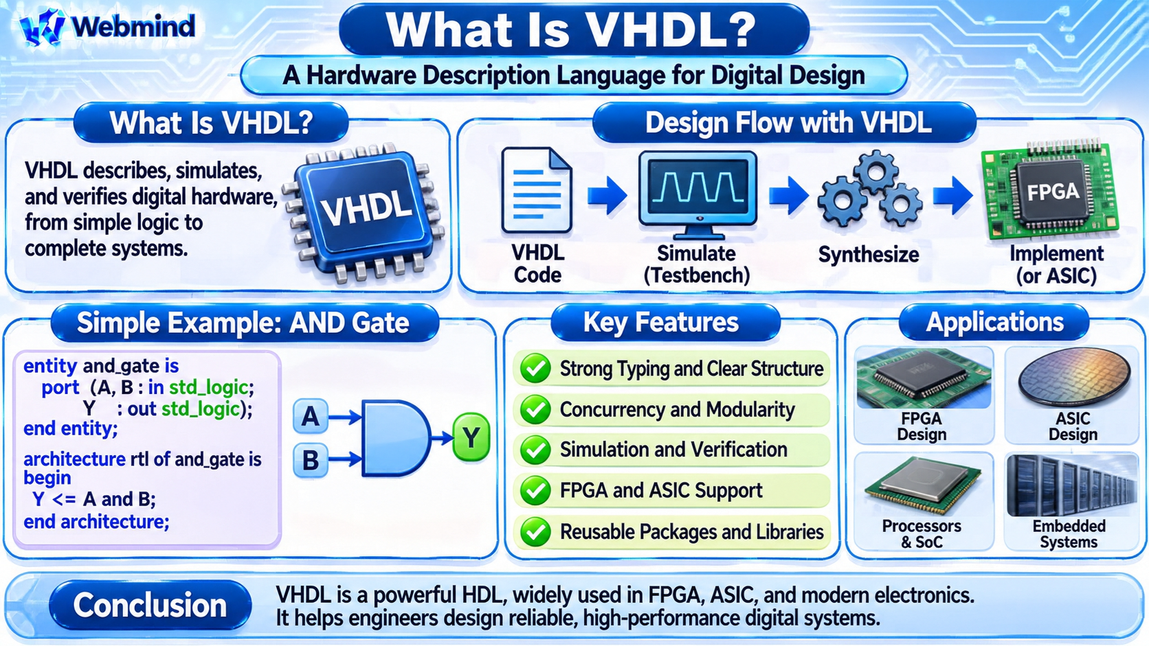
VHDL, or VHSIC Hardware Description Language, is a hardware description language used to design, simulate, and verify digital electronic circuits.
VHSIC stands for Very High Speed Integrated Circuit, reflecting the program through which the language was originally developed.
VHDL is widely used in FPGA development, ASIC design, digital signal processing, aerospace systems, industrial electronics, and embedded hardware.
Unlike conventional programming languages such as C or Python, which primarily describe instructions executed by a processor, VHDL describes the behavior and structure of digital circuits.
Engineers use VHDL to design logic gates, registers, counters, Finite State Machines (FSMs), arithmetic circuits, and complete digital systems.
How Does VHDL Work?
VHDL allows engineers to describe digital hardware using signals, processes, and concurrent statements.
For example, a designer can describe an AND gate with two inputs, A and B, and one output, Y.
The VHDL statement:
Y <= A and B;
describes the logical relationship between the signals.
When both inputs are 1, the output becomes 1. Otherwise, the output is 0.
Unlike ordinary sequential software execution, multiple VHDL hardware processes can operate concurrently.
This reflects how physical electronic circuits operate.
After writing VHDL, engineers use Electronic Design Automation (EDA) tools to simulate the design, synthesize it into hardware, and verify its timing.
What Are Entity and Architecture in VHDL?
A VHDL design commonly separates a hardware component into an entity and an architecture.
Entity: Defines the external interface of a component, including its input and output ports.
Architecture: Describes the internal behavior or structure of the component.
For example, an entity named and_gate may define two input ports and one output port.
Its architecture can contain the statement:
Y <= A and B;
This separation allows a component’s interface to remain consistent while its internal implementation changes.
Large VHDL projects contain many connected entities and architectures that work together to form a complete digital system.
What Are Signals in VHDL?
Signals represent connections and values within a digital hardware design.
A signal may carry a single binary value or a group of bits.
VHDL commonly uses the IEEE std_logic type for individual digital signals and std_logic_vector for collections of bits.
For example:
signal data : std_logic_vector(7 downto 0);
This declares an eight-bit signal named data.
The std_logic type supports multiple simulation values, including logical zero, logical one, unknown, and high-impedance states.
These additional values help simulation tools represent conditions that cannot be described using only 0 and 1.
A VHDL signal does not automatically become a physical register. The resulting hardware depends on how the signal is driven.
Combinational Logic in VHDL
Combinational logic produces outputs based on current input values.
Examples include logic gates, multiplexers, decoders, and arithmetic circuits.
For example, a two-input XOR function can be described as:
Y <= A xor B;
A multiplexer can be described using conditional signal assignments or a process containing an if or case statement.
For a two-input multiplexer, the output selects D0 or D1 according to a select signal.
In VHDL, concurrent signal assignments are evaluated as part of the overall hardware model.
When using processes for combinational logic, designers must assign outputs for every relevant condition to avoid unintended storage elements.
Sequential Logic in VHDL
Sequential logic stores information and changes state according to clock events.
Examples include flip-flops, registers, counters, and state machines.
A typical D flip-flop is described using a clocked process.
Inside the process, the expression:
if rising_edge(clk) then
identifies a rising clock edge.
The statement:
q <= d;
can then be used to capture the input data.
In a synthesizable clocked process, this describes a register that stores the value of D at each rising clock edge.
Sequential circuits are essential for maintaining state and coordinating operations in synchronous digital systems.
What Is a Process in VHDL?
A process is a VHDL construct containing sequential statements that execute when the process is activated.
Although statements within a process execute according to VHDL simulation rules, separate processes can operate concurrently.
Processes are commonly used to describe combinational and clocked sequential logic.
For example, a combinational process can calculate an ALU output from its operands and operation selector.
A clocked process can update registers when a clock edge occurs.
In modern VHDL, process(all) can automatically include signals read by a combinational process in its sensitivity list.
This helps reduce errors caused by incomplete sensitivity lists.
What Is the Difference Between Signals and Variables?
VHDL provides both signals and variables.
Signals: Represent values communicated between concurrent parts of a design. Signal assignments generally schedule updates according to VHDL simulation semantics.
Variables: Are used within processes, subprograms, and other permitted declarative regions. Variable assignments take effect immediately within the sequential execution of those statements.
For example, a variable assignment uses the operator :=, while a signal assignment uses <=.
This difference is important when describing arithmetic calculations and sequential hardware behavior.
Both signals and variables may be used in synthesizable VHDL, depending on how they are declared and assigned.
How Do You Build a Counter in VHDL?
A binary counter is a common beginner project in FPGA development.
A counter stores a numerical value and increments it when a clock event occurs.
VHDL commonly uses the unsigned type from the IEEE numeric_std package for unsigned arithmetic.
For example, a clocked counter may contain:
count <= count + 1;
If count is an eight-bit unsigned signal, it can represent values from 0 through 255.
A conventional wrapping counter returns to zero after reaching its maximum value.
Practical designs often include reset and enable signals.
During synthesis, the counter is implemented using flip-flops and arithmetic logic, potentially including dedicated FPGA carry-chain resources.
What Is a VHDL Testbench?
A testbench is a simulation environment used to verify a hardware design before implementation.
It generates input signals, observes outputs, and checks whether the circuit behaves as expected.
For example, a testbench for a two-input AND gate can apply all four possible binary input combinations.
The expected results are compared with the circuit’s actual outputs.
VHDL provides assertions and reporting statements that can automatically identify incorrect behavior.
Testbenches can also generate clock signals, apply reset sequences, and simulate communication transactions.
Simulation-only testbench code is generally not synthesized into physical hardware.
What Is VHDL Simulation?
VHDL simulation evaluates a hardware description over simulated time.
A simulator processes signal changes, activates relevant processes, and updates values according to the language’s event-scheduling rules.
For example, a designer can simulate a counter and examine its output waveform after each clock edge.
Simulation helps engineers identify functional errors before programming an FPGA or manufacturing an ASIC.
Common VHDL simulation tools include GHDL, Questa, and other commercial EDA simulators.
However, functional RTL simulation alone does not guarantee that the physical implementation will satisfy all setup-time, hold-time, and clock-frequency requirements.
What Is VHDL Synthesis?
Synthesis converts synthesizable VHDL descriptions into hardware structures.
For FPGA development, the synthesis tool maps the design onto LUTs, flip-flops, Block RAM, DSP blocks, and other programmable resources.
For ASIC development, synthesis maps the design into standard cells from a semiconductor technology library.
For example, a VHDL arithmetic expression may become an adder circuit, while an edge-triggered assignment may become a flip-flop.
Not every VHDL feature is synthesizable.
Simulation delays, file operations, and certain testbench constructs may be useful for verification but do not directly represent implementable hardware.
Engineers must distinguish between hardware-oriented RTL and simulation-only descriptions.
VHDL in FPGA Development
VHDL is widely used to design programmable digital hardware.
A typical FPGA development process includes RTL design, simulation, synthesis, placement and routing, timing analysis, and bitstream generation.
For example, a designer may describe a UART controller using VHDL.
Simulation verifies its communication behavior.
Synthesis maps the design onto FPGA logic resources.
Placement and routing tools assign those resources to physical locations and connect them.
Static Timing Analysis checks the completed implementation against clock and timing constraints.
Finally, the configuration bitstream is generated and loaded into the FPGA.
Development environments such as AMD Vivado and Intel Quartus Prime support VHDL-based workflows.
VHDL in ASIC Development
VHDL can also be used to develop Application-Specific Integrated Circuits.
Engineers describe the required digital functionality using RTL.
EDA tools simulate and verify the design before synthesis.
Synthesis converts the hardware description into a network of logic gates and sequential cells.
Physical design tools then perform floorplanning, placement, clock-tree synthesis, and routing.
The completed layout must satisfy manufacturing design rules and electrical timing requirements.
After verification, the design is prepared for tape-out.
Because ASIC manufacturing is expensive, thorough functional and timing verification is essential.
What Are Packages and Libraries in VHDL?
VHDL uses libraries and packages to organize reusable design information.
A package can contain data types, constants, functions, procedures, and component declarations.
For example, the IEEE numeric_std package provides arithmetic support for the signed and unsigned types.
A package can also define common data structures and functions shared by multiple hardware modules.
Libraries provide a way to organize compiled design units.
These features are important when developing large FPGA or ASIC projects containing many components.
They help engineers maintain consistent definitions and reuse verified design code.
What Is a Finite State Machine in VHDL?
A Finite State Machine is a digital control structure that operates through a defined set of states.
VHDL supports FSM development using enumerated types, clocked processes, and combinational logic.
For example, a controller may contain the states IDLE, RUNNING, and DONE.
A clocked process stores the current state.
Combinational logic determines the next state according to input conditions.
Output logic generates control signals.
FSMs are used in processors, communication interfaces, robotics, memory controllers, and industrial automation systems.
VHDL’s strongly typed features can help make state definitions and transitions clear.
VHDL vs. Verilog
VHDL and Verilog are two major hardware description languages.
Both can describe combinational logic, sequential circuits, and complex digital systems.
VHDL: Uses a strongly typed language structure with explicit declarations and a syntax influenced by Ada.
Verilog: Uses a more compact syntax influenced by C-like programming languages.
Both support simulation and synthesis.
Modern SystemVerilog extends Verilog with additional hardware design and verification capabilities.
The choice between VHDL and Verilog often depends on existing projects, engineering preferences, industry requirements, and available tools.
Neither language is inherently faster in hardware. Performance depends on the resulting circuit and its implementation.
What Is VHDL-2008?
VHDL has evolved through several revisions of the IEEE 1076 standard.
VHDL-2008 introduced improvements that make the language more convenient for hardware design and verification.
These include enhanced generic capabilities, improvements to packages, and more flexible process sensitivity handling.
For example, process(all) simplifies the description of combinational logic by automatically accounting for signals read by the process.
Later revisions, including VHDL-2019, introduced further language improvements.
However, support for newer features varies between simulators and synthesis tools.
Engineers should check the language version supported by their development environment.
Can You Learn VHDL Without an FPGA Board?
Yes. VHDL can be learned through simulation without purchasing an FPGA development board.
A beginner can start by describing simple logic gates and verifying their truth tables.
The next projects may include a multiplexer, decoder, counter, and finite state machine.
Open-source tools such as GHDL can simulate VHDL designs, while waveform viewers such as GTKWave can help examine signal changes.
After learning the fundamentals, students can move to synthesis and FPGA hardware implementation.
This simulation-first approach allows beginners to understand digital circuit behavior before working with physical development boards.
Advantages of VHDL
Strong Typing: Helps detect certain type mismatches and design errors during compilation.
Hardware Concurrency: Describes multiple circuits operating simultaneously.
Modular Design: Entities, architectures, packages, and libraries support organized hardware development.
Simulation and Verification: Allows engineers to test circuit behavior before implementation.
FPGA and ASIC Compatibility: Supports programmable hardware and custom semiconductor design.
Design Reuse: Verified hardware components can be integrated into larger systems.
These advantages make VHDL useful in professional digital engineering.
Limitations of VHDL
VHDL also presents several challenges.
Learning Curve: Its syntax and strong typing can require more explanation for beginners.
Verbose Code: Some simple hardware descriptions require more text than equivalent Verilog implementations.
Tool Compatibility: Support for language revisions and features varies among EDA tools.
Hardware Knowledge Required: Writing VHDL requires an understanding of digital logic and timing.
Synthesis Restrictions: Not all language constructs can be converted into physical hardware.
Despite these limitations, VHDL remains a powerful language for designing reliable digital systems.
Where Is VHDL Used?
VHDL is used in many areas of electronic engineering.
FPGA Development: Programmable logic, embedded controllers, and communication interfaces.
ASIC Design: Custom digital integrated circuits and specialized processors.
Aerospace and Defense: Digital hardware used in selected safety-critical and high-reliability applications.
Industrial Automation: Control systems, motor interfaces, and digital equipment.
Digital Signal Processing: Filters, arithmetic pipelines, and signal-processing systems.
Telecommunications: Protocol controllers and specialized communication hardware.
Research and Education: Digital logic, computer architecture, and semiconductor design.
Its combination of hardware modeling and verification capabilities makes it valuable in both educational and professional applications.
Conclusion
VHDL is a Hardware Description Language used to design, simulate, and implement digital electronic circuits.
It describes hardware using entities, architectures, signals, processes, and concurrent statements.
VHDL supports combinational logic, sequential circuits, registers, counters, finite state machines, and complete digital systems.
It is widely used in FPGA development, ASIC engineering, industrial electronics, and embedded hardware.
Understanding VHDL provides an important foundation for studying Boolean algebra, digital logic, Verilog, SystemVerilog, FPGA architecture, and modern semiconductor design.