Introduction
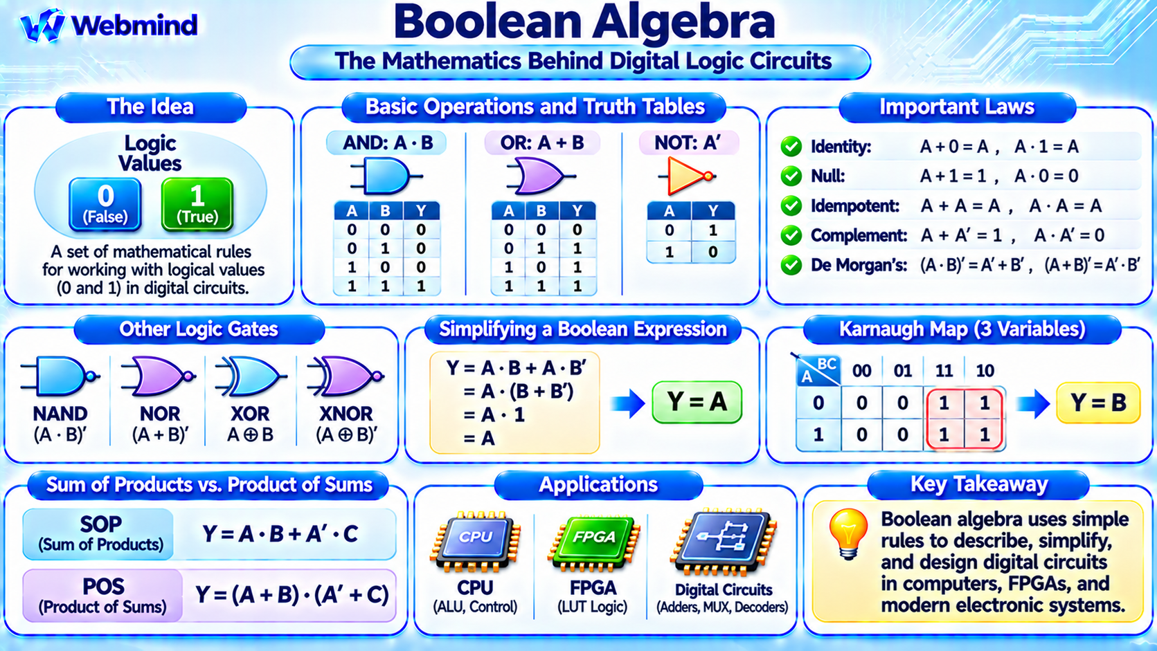
Boolean algebra is a branch of mathematics that uses two logical values, typically represented by 0 and 1, to describe and manipulate logical expressions.
It forms the mathematical foundation of digital electronics, logic gates, computer processors, and digital circuit design.
Unlike ordinary algebra, which works with numerical quantities, Boolean algebra operates on logical values such as true and false.
Boolean algebra was developed by mathematician George Boole in the 19th century.
It later became essential to digital computing because electronic circuits can implement Boolean operations using transistors and logic gates.
Modern CPUs, GPUs, microcontrollers, FPGAs, and ASICs all rely on Boolean logic.
How Does Boolean Algebra Work?
Boolean algebra uses variables that can have only two values: 0 or 1.
These values represent logical states rather than ordinary numerical quantities.
Three fundamental operations form the basis of Boolean algebra: AND, OR, and NOT.
AND: Produces 1 only when both inputs are 1.
OR: Produces 1 when at least one input is 1.
NOT: Reverses the logical value of an input.
For example, consider two Boolean variables, A and B.
The expression A AND B produces 1 only when A = 1 and B = 1.
Boolean expressions can combine these operations to describe more complex logical conditions.
Digital circuits implement these expressions using electronic logic gates.
The Three Basic Boolean Operations
AND Operation
The AND operation is commonly represented using a multiplication symbol or a dot.
Y = A · B
For two Boolean inputs, the results are:
0 AND 0 = 0
0 AND 1 = 0
1 AND 0 = 0
1 AND 1 = 1
An AND operation requires all conditions to be true.
OR Operation
The OR operation is commonly represented using the plus symbol.
Y = A + B
The results are:
0 OR 0 = 0
0 OR 1 = 1
1 OR 0 = 1
1 OR 1 = 1
In Boolean algebra, 1 + 1 equals 1 because the plus symbol represents logical OR, not ordinary arithmetic addition.
NOT Operation
The NOT operation produces the opposite logical value.
It may be represented by a bar over the variable, an apostrophe, or a logical negation symbol.
For example:
Y = A’
If A = 0, then A’ = 1.
If A = 1, then A’ = 0.
The NOT operation is implemented using an inverter in digital circuits.
What Is a Boolean Expression?
A Boolean expression combines logical variables and operators to describe a logical function.
For example:
Y = A · B + C
This expression means that the output is 1 when both A and B are 1, or when C is 1.
Boolean expressions can describe circuits containing many interconnected logic gates.
For example, an electronic control system might activate a motor only when a start button is pressed and a safety condition is satisfied.
Boolean algebra allows engineers to represent such requirements mathematically before implementing them in hardware.
What Is a Truth Table?
A truth table lists every possible combination of input values and the corresponding output of a Boolean expression.
For example, consider:
Y = A · B
The four possible input combinations are:
A = 0, B = 0 → Y = 0
A = 0, B = 1 → Y = 0
A = 1, B = 0 → Y = 0
A = 1, B = 1 → Y = 1
A Boolean function with n binary inputs has 2ⁿ possible input combinations.
Truth tables are useful for verifying logic expressions, comparing circuits, and designing digital hardware.
Important Laws of Boolean Algebra
Boolean algebra includes several mathematical laws that allow logical expressions to be simplified.
Identity Laws
A + 0 = A
A · 1 = A
These laws show that OR with 0 and AND with 1 do not change a Boolean value.
Null Laws
A + 1 = 1
A · 0 = 0
These expressions show how logical constants determine certain operation results.
Idempotent Laws
A + A = A
A · A = A
Repeating the same Boolean variable does not change the logical result.
Complement Laws
A + A’ = 1
A · A’ = 0
A Boolean variable and its complement cannot both be 1.
Commutative Laws
A + B = B + A
A · B = B · A
The order of the inputs does not change the result of AND or OR.
Associative Laws
(A + B) + C = A + (B + C)
(A · B) · C = A · (B · C)
Grouping operations differently does not change the result.
Distributive Laws
A · (B + C) = A · B + A · C
A + (B · C) = (A + B) · (A + C)
These laws are especially useful when transforming and simplifying digital logic expressions.
What Are De Morgan’s Laws?
De Morgan’s laws are two important Boolean algebra rules used to transform expressions involving AND, OR, and NOT.
The first law states:
(A · B)’ = A’ + B’
The NOT of an AND operation is equivalent to the OR of the complemented inputs.
The second law states:
(A + B)’ = A’ · B’
The NOT of an OR operation is equivalent to the AND of the complemented inputs.
These laws are widely used in logic circuit design because they allow engineers to convert between different gate implementations.
For example, a NAND function can be expressed as an OR function with complemented inputs.
De Morgan’s laws are particularly useful when designing circuits using NAND and NOR gates.
How to Simplify Boolean Expressions
Boolean algebra can reduce the complexity of digital logic circuits.
Consider the expression:
Y = A · B + A · B’
Both terms contain A, so the expression can be factored:
Y = A · (B + B’)
Because B + B’ = 1:
Y = A · 1
Therefore:
Y = A
The original expression appears to require multiple logic operations, but the simplified circuit only needs to pass the value of A to the output.
This illustrates how Boolean simplification can eliminate unnecessary gates.
However, a mathematically simpler expression does not always produce the fastest physical circuit. Timing, fanout, routing, and implementation technology also matter.
What Are NAND and NOR Gates?
NAND and NOR are derived from the fundamental Boolean operations.
NAND: Performs AND followed by NOT.
Y = (A · B)’
NOR: Performs OR followed by NOT.
Y = (A + B)’
Both NAND and NOR are universal logic gates.
This means that any Boolean function can be implemented using only NAND gates or only NOR gates.
For example, connecting both inputs of a NAND gate to the same signal produces an inverter.
Universal gates are important because they allow complex logical functions to be constructed using repeated instances of a basic circuit structure.
What Is XOR in Boolean Algebra?
XOR stands for Exclusive OR.
For two Boolean inputs, XOR produces 1 when the inputs are different.
The XOR operation can be expressed using AND, OR, and NOT:
A XOR B = A’ · B + A · B’
For example:
0 XOR 0 = 0
0 XOR 1 = 1
1 XOR 0 = 1
1 XOR 1 = 0
XOR is especially important in binary arithmetic.
A half adder uses XOR to calculate the sum bit and AND to calculate the carry bit.
Sum = A XOR B
Carry = A · B
This connects Boolean mathematics directly to arithmetic circuits inside a CPU.
What Is a Karnaugh Map?
A Karnaugh map, commonly called a K-map, is a graphical technique used to simplify Boolean expressions.
It arranges truth-table output values into a grid so that logically adjacent input combinations can be grouped.
Each group represents terms that can be combined to eliminate unnecessary variables.
For example, a four-variable Boolean function has 16 possible input combinations, which can be placed into a four-by-four Karnaugh map.
By grouping adjacent ones, engineers can derive simplified Sum-of-Products expressions.
Karnaugh maps are particularly useful for small Boolean functions.
For larger designs, automated logic minimization and synthesis tools are generally more practical.
Sum of Products vs. Product of Sums
Boolean functions are commonly represented using two standard forms.
Sum of Products (SOP): An OR operation combining multiple AND terms.
For example:
Y = A · B + A’ · C
Product of Sums (POS): An AND operation combining multiple OR terms.
For example:
Y = (A + B) · (A’ + C)
These forms provide systematic ways to represent Boolean functions.
Truth tables can be converted into canonical SOP or POS expressions, which can then be simplified.
EDA tools use related logic optimization techniques when converting hardware descriptions into physical gate networks.
Boolean Algebra in CPUs and Digital Circuits
Boolean algebra provides the mathematical rules used to design digital logic circuits.
Inside a CPU, Boolean functions control arithmetic operations, comparisons, instruction decoding, and data selection.
ALU: Implements arithmetic and bitwise logical operations.
Control Unit: Uses Boolean conditions to generate processor control signals.
Multiplexers: Select data sources based on logical control inputs.
Decoders: Convert binary input patterns into control outputs.
Registers and State Machines: Combine Boolean logic with storage elements to implement sequential behavior.
Although modern processors contain billions of transistors, their digital logic can be described using combinations of Boolean functions and state transitions.
Boolean Algebra in FPGAs
Boolean algebra is particularly important in FPGA development.
An FPGA contains configurable logic resources, including Look-Up Tables (LUTs), registers, and programmable interconnections.
A LUT can implement a Boolean function by storing its truth-table outputs.
For example, a two-input AND function produces the output pattern 0, 0, 0, 1 for input combinations 00, 01, 10, and 11.
A compatible LUT can store these four output values and select the correct one using its two inputs.
The same LUT can be reconfigured to implement OR, XOR, NAND, or other Boolean functions.
When engineers write Verilog or VHDL, synthesis software uses Boolean optimization to map the described logic onto FPGA resources.
Understanding Boolean algebra therefore helps explain how digital circuit descriptions become real FPGA hardware.
Boolean Algebra vs. Binary Arithmetic
Boolean algebra and binary arithmetic both use zeros and ones, but they serve different purposes.
Boolean Algebra: Treats 0 and 1 as logical values and uses operations such as AND, OR, and NOT.
Binary Arithmetic: Treats binary digits as parts of numerical values and performs arithmetic operations such as addition and subtraction.
For example, in Boolean algebra:
1 OR 1 = 1
In binary arithmetic:
1 + 1 = 10₂
The difference is important because the same symbols can represent different operations depending on the mathematical context.
Digital processors use Boolean logic circuits to implement binary arithmetic operations.
Why Is Boolean Algebra Important?
Boolean algebra makes it possible to describe complex digital behavior using simple mathematical rules.
It provides techniques for simplifying logic expressions, reducing unnecessary circuit operations, and verifying digital hardware designs.
Boolean algebra is also used in programming conditions, database queries, search expressions, and control systems.
In computer engineering, it forms the foundation of logic synthesis, circuit optimization, FPGA programming, and ASIC development.
Understanding Boolean algebra is therefore essential for moving from basic logic gates to complete digital computing systems.
Conclusion
Boolean algebra is a mathematical system based on two logical values, 0 and 1, and operations such as AND, OR, and NOT.
Its laws allow engineers to analyze, transform, and simplify digital logic expressions.
Important concepts include truth tables, De Morgan’s laws, NAND and NOR gates, XOR operations, Karnaugh maps, and Boolean expression minimization.
Modern CPUs, microcontrollers, FPGAs, and ASICs use circuits whose behavior can be described through Boolean logic.
Understanding Boolean algebra provides an essential foundation for studying logic gates, digital circuit design, binary arithmetic, Verilog, FPGA architecture, and modern computer engineering.