Introduction
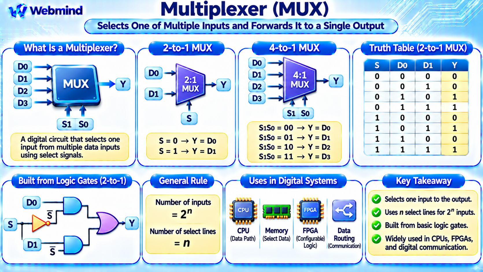
A multiplexer, commonly called a MUX, is a digital logic circuit that selects one input from multiple data inputs and forwards it to a single output.
The selected input is determined by one or more control signals known as select lines.
Multiplexers are fundamental building blocks of digital electronics.
They are widely used in CPUs, GPUs, microcontrollers, FPGAs, ASICs, communication systems, and digital signal processing circuits.
For example, a processor may use a multiplexer to select which register value should be sent to its Arithmetic Logic Unit (ALU).
By allowing several data sources to share one output path, multiplexers make digital circuits more flexible and efficient.
How Does a Multiplexer Work?
A multiplexer operates like an electronically controlled switch.
It receives multiple data inputs, a set of select signals, and produces one output.
The select signals determine which input is connected logically to the output.
For example, a 2-to-1 multiplexer has two data inputs, D0 and D1, one select input, S, and one output, Y.
When S = 0, the output follows D0.
When S = 1, the output follows D1.
The multiplexer does not store the selected data.
It is a combinational circuit, meaning its output depends on the current input and select values, after accounting for propagation delay.
What Is a 2-to-1 Multiplexer?
A 2-to-1 multiplexer is the simplest commonly used multiplexer.
It has two data inputs, one select input, and one output.
Its operation can be described as follows:
S = 0 → Y = D0
S = 1 → Y = D1
The corresponding Boolean expression is:
Y = (NOT S AND D0) OR (S AND D1)
Using Boolean algebra notation:
Y = S’ · D0 + S · D1
This expression shows how the select signal determines which input contributes to the output.
A 2-to-1 multiplexer can be implemented using two AND gates, one OR gate, and one NOT gate.
Other implementations may use NAND gates, transmission gates, or specialized CMOS transistor structures.
What Is a 4-to-1 Multiplexer?
A 4-to-1 multiplexer selects one of four data inputs.
It has four inputs, D0 through D3, two select signals, S1 and S0, and one output.
The select signals form a two-bit binary number that identifies the selected input.
S1S0 = 00 → Y = D0
S1S0 = 01 → Y = D1
S1S0 = 10 → Y = D2
S1S0 = 11 → Y = D3
A 4-to-1 multiplexer can be constructed using three 2-to-1 multiplexers arranged in two stages.
Larger multiplexers can be created by combining smaller multiplexer circuits.
For example, an 8-to-1 multiplexer requires three select bits, while a 16-to-1 multiplexer requires four select bits.
How Many Select Lines Does a Multiplexer Need?
The number of select lines depends on the number of inputs.
For a conventional multiplexer with 2ⁿ inputs, n select lines are required.
The relationship is:
Number of Inputs = 2ⁿ
Where n represents the number of select bits.
For example:
2-to-1 MUX: 1 select line.
4-to-1 MUX: 2 select lines.
8-to-1 MUX: 3 select lines.
16-to-1 MUX: 4 select lines.
32-to-1 MUX: 5 select lines.
Multiplexers with a non-power-of-two number of inputs are also possible.
Such circuits generally require enough select bits to identify every input, with unused select combinations handled according to the design.
How Is a Multiplexer Built from Logic Gates?
A multiplexer can be implemented using fundamental Boolean operations.
Consider the 2-to-1 MUX expression:
Y = S’ · D0 + S · D1
The NOT gate produces the complement of S.
One AND gate combines D0 with S’, while another AND gate combines D1 with S.
The outputs of these AND gates are connected to an OR gate.
When S = 0, the first AND path is enabled and the second is disabled.
When S = 1, the second AND path is enabled and the first is disabled.
This arrangement implements the required input-selection function.
In modern integrated circuits, synthesis tools may implement the same behavior using optimized transistor networks or dedicated multiplexer standard cells.
Multiplexers in CPUs
Multiplexers are used extensively inside processors because CPUs must constantly select between different sources of data.
For example, an ALU may receive operands from several registers, immediate values, or forwarded results.
A multiplexer selects the appropriate operand according to the instruction being executed.
Multiplexers are also used in processor control logic.
ALU Input Selection: Chooses between register operands and immediate values.
Register Write-Back: Selects whether a register receives an ALU result, loaded data, or another value.
Program Counter Control: Selects the next instruction address, such as a sequential address or branch target.
Data Forwarding: Chooses recently computed results to resolve certain data dependencies in pipelined processors.
These functions make multiplexers essential to modern CPU architecture.
Multiplexers in FPGAs
Multiplexers are also important components of FPGA architecture.
Modern FPGAs contain configurable logic resources, registers, and programmable routing networks.
Multiplexer-like selection structures are used extensively to implement configurable signal paths.
For example, a Look-Up Table (LUT) can be understood conceptually as a collection of stored truth-table values and a selection network.
A LUT with four inputs can represent a Boolean function with sixteen possible input combinations.
The input bits determine which stored output value is selected.
The exact physical implementation of a LUT varies by FPGA architecture, but multiplexing is a useful model for understanding how LUTs implement Boolean functions.
Programmable routing structures also use configurable switches and selection mechanisms to connect logic resources.
Multiplexer vs. Demultiplexer
A multiplexer and a demultiplexer perform complementary routing functions.
Multiplexer (MUX): Selects one of several data inputs and forwards it to one output.
Demultiplexer (DEMUX): Takes one data input and directs it to one of several outputs according to select signals.
For example, a 4-to-1 MUX combines four possible input sources into one selected output path.
A 1-to-4 DEMUX directs one input signal toward one of four output paths.
Both circuits are used in communication systems, data routing, memory interfaces, and digital control logic.
However, multiplexers and demultiplexers do not necessarily provide bidirectional electrical connections. Their behavior depends on the circuit implementation.
Multiplexer vs. Decoder
A decoder converts a binary input code into a set of output signals.
For example, a 2-to-4 decoder has two binary inputs and four outputs.
For each valid input combination, one corresponding output is activated in a conventional active-high decoder.
A multiplexer uses select signals to choose one data input.
A decoder instead identifies a selected output condition from a binary code.
Decoders can be used as building blocks within multiplexer implementations, but the two circuits serve different purposes.
What Is Propagation Delay in a Multiplexer?
A real multiplexer does not change its output instantaneously.
Propagation delay is the time required for an input or select signal change to affect the output.
This delay depends on circuit structure, transistor characteristics, output load, supply voltage, and manufacturing technology.
Larger multiplexers may contain multiple logic stages, increasing the delay through the selection network.
In a high-speed processor, excessive multiplexer delay can limit the maximum operating clock frequency.
Digital designers therefore consider timing constraints when selecting multiplexer structures.
EDA tools can optimize multiplexer implementations to balance timing, power consumption, and circuit area.
Multiplexers in Communication Systems
Multiplexers are widely used in data communication and signal processing.
They allow multiple data sources to share a common processing or transmission path.
For example, a digital system may select data from several sensors and forward one selected stream to a processing unit.
Multiplexer circuits can also select between different communication channels or internal data paths.
However, a basic digital logic multiplexer should not be confused with every form of communication multiplexing.
Time-Division Multiplexing (TDM), Frequency-Division Multiplexing (FDM), and other communication techniques involve additional timing, frequency allocation, or signal-processing mechanisms.
A digital MUX can be part of these systems, but it does not implement all their functions by itself.
How Is a Multiplexer Described in Verilog?
Hardware Description Languages such as Verilog allow designers to describe multiplexers directly.
For example, a 2-to-1 multiplexer can be represented using a conditional expression:
assign y = s ? d1 : d0;
This means that when s is logically true, y receives d1. Otherwise, y receives d0, assuming ordinary two-state inputs.
In Verilog simulation, unknown values may require additional consideration because the language supports four-state logic.
Multiplexers can also be described using if statements or case statements in combinational logic blocks.
During synthesis, an EDA tool converts the description into appropriate hardware resources.
For an FPGA, the implementation may use LUTs or dedicated selection structures.
For an ASIC, synthesis may use standard-cell multiplexers or equivalent logic gates.
Advantages of Multiplexers
Efficient Data Selection: Multiple data sources can share one output path.
Reduced Hardware Duplication: Selection logic can help avoid duplicating processing resources.
Flexible Circuit Design: Control signals determine which data source is active.
Scalability: Larger multiplexers can be constructed from smaller selection circuits.
Broad Compatibility: Multiplexers can be implemented using standard logic gates, CMOS transistors, or FPGA resources.
These advantages make multiplexers fundamental components of digital systems.
Limitations of Multiplexers
Multiplexers also introduce design considerations.
Propagation Delay: Selection logic adds delay to the data path.
Control Complexity: Large multiplexers require additional select signals or decoding logic.
Power Consumption: Switching activity consumes dynamic power.
Circuit Area: Large selection networks require more gates, transistors, or programmable resources.
Signal Glitches: Changes in select signals or data inputs may produce temporary output transitions, depending on the circuit implementation.
Engineers address these issues through appropriate circuit structures, timing analysis, and careful control-signal design.
Where Are Multiplexers Used?
Multiplexers appear throughout modern digital hardware.
CPUs: Select operands, register data, instruction addresses, and execution results.
GPUs: Route data between processing units and internal functional blocks.
Microcontrollers: Select peripheral signals, internal data paths, and control inputs.
FPGAs: Support configurable logic and programmable routing resources.
ASICs: Implement data selection and control functions in specialized hardware.
Memory Systems: Select addresses, data sources, and communication paths.
Digital Communication: Support channel selection and signal-routing functions.
Understanding multiplexers helps explain how complex systems move data between hardware components.
Conclusion
A multiplexer is a combinational logic circuit that selects one input from multiple data sources and forwards it to a single output.
Select signals determine which input is chosen, allowing digital circuits to share data paths and processing resources.
Common configurations include 2-to-1, 4-to-1, 8-to-1, and 16-to-1 multiplexers.
Multiplexers are fundamental to CPU data paths, FPGA LUTs, memory interfaces, communication systems, and digital control circuits.
Understanding multiplexers provides an important foundation for studying Boolean algebra, logic gates, digital circuit design, Verilog, FPGA architecture, ASIC development, and modern computer engineering.