1.Basic Operations of Boolean Algebra
1.1) The Basic Concept of Boolean Algebra
Logic refers to the laws that govern the causality between things. In order to avoid using cumbersome words to describe logical problems, logical algebra uses logical variables and logical functions to describe the causes (conditions) and results of events, respectively.
Logical variables are similar to variables in ordinary algebra and can be represented by letters such as A, B, C, and x, y, z. However, the difference lies in the fact that in ordinary algebra, variables can take on any value, while in logical algebra, variables and constants can only take on two values: logical 0 and logical 1. Therefore, it is called binary logic. It is important to note that logical 0 and logical 1 do not represent quantities but rather represent the two opposing states of a contradiction. For example, they can represent the true and false values of an event, the on and off states of a switch, the high and low levels of a signal, and so on.
Logical functions are similar to functions in ordinary algebra. They represent the dependent variable that changes with the variation of independent variables. Therefore, if the conditions and results of an event are represented by independent and dependent variables, the causal relationship of that event can be described using logical functions.
The way a digital circuit responds to inputs is called the logic of the circuit. There exists a logical relationship between the output and input variables of any digital circuit, which can be described using logical functions. For example, for a certain circuit, if the values of input logical variables A, B, C, … are determined, the value of the output logical variable F is also uniquely determined. In this case, F can be called a logical function of A, B, C, …, and can be denoted as F = f(A, B, C, …).
1.2) The Three Basic Logical Operations
The basic operations in logical algebra are AND, OR, and NOT, which can be implemented using corresponding logic gates.
- AND Operation (Logical Multiplication)
The AND operation (logical multiplication) represents a logical relationship where the result only occurs when all the conditions determining an event’s outcome are simultaneously present. For example, in the series switch circuit shown in the diagram below,
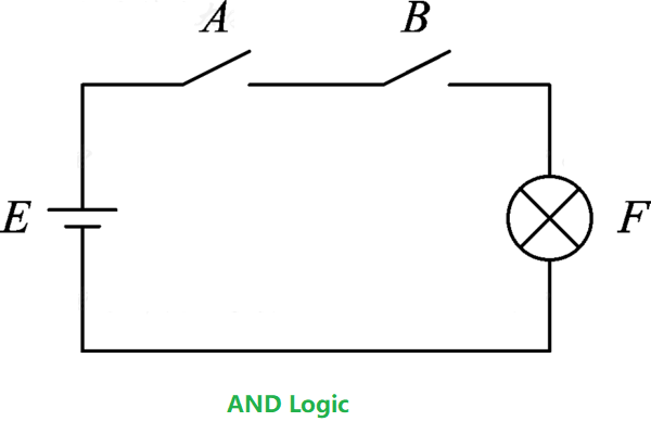
the light F will only turn on when both switch A and switch B are closed. This relationship between the light being on and the switches being closed is called an AND logic. If we assign the value 1 to the closed state of switches A and B, and 0 to the open state, and consider the light F being on as 1 and off as 0, the relationship between F and A, B using AND logic can be described using the truth table shown below.
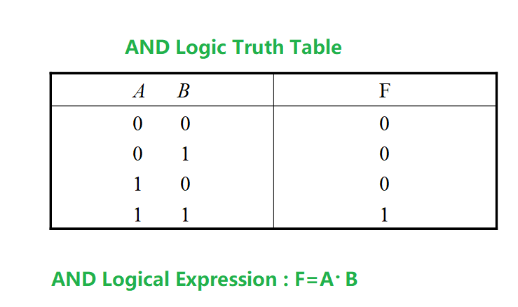
A truth table is a tabular representation that lists all possible combinations of input logical variables with their corresponding output function values.
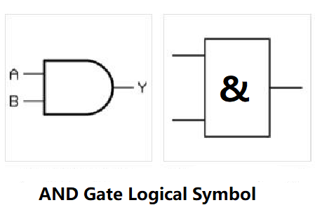
In logical algebra, the AND logic operation is also referred to as the AND operation or logical multiplication. The symbol “·” is used to represent logical multiplication, and it is often omitted when there is no confusion. In some literature, the symbols ∧, ∩, and & are also used to represent logical multiplication.
2. OR Operation ( Logical Addition)
The OR operation, also known as logical addition, represents a logical relationship where the result occurs if at least one of the conditions determining an event’s outcome is satisfied. For example, in the parallel switch circuit shown in following figure,
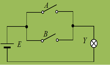
if either switch A or switch B is closed, the light Y will turn on. This relationship between the light being on and the switches being closed is called an OR logic. The OR logic relationship between Y and A, B can be described using the following truth table.

The OR logic can be represented using logical expressions: F=A+B
If we consider the diode as an ideal switch and define a high voltage as logic 1 and a low voltage as logic 0, then the truth table representing the logical relationship between F, A, and B would be the same as OR Truth Table. Therefore, the functionality of F = A + B is achieved.
In this case, when either A or B (or both) is at logic 1 (high voltage), the diodes connected to A and B will be forward-biased, allowing current to flow through and creating a logical connection to F. When both A and B are at logic 0 (low voltage), the diodes will be reverse-biased, preventing current flow and isolating F from the inputs. Thus, the circuit behaves like an OR gate and implements the logical addition (OR logic) operation F = A + B.
The OR logic operation is also referred to as the OR operation or logical addition. The symbol “+” is used to represent logical addition. In some literature, the symbols “∨”, “∪”, and others are also used to denote logical addition.
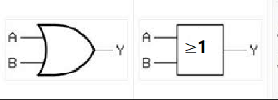
The unit circuit that implements the OR logic is called an OR gate. The logical symbol for an OR gate is represented as above figure.
3. NOT Operation
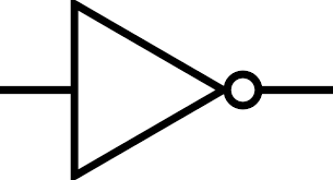
The NOT operation, also known as logical negation, represents the logical negation or denial. It establishes a logical relationship where the result does not occur when the condition is fulfilled, and it does occur when the condition is not fulfilled.
For example, in the switch circuit shown in the diagram below, the light Y will only turn on when switch A is open (disconnected), and it will turn off when switch A is closed (connected). The state of the light Y is always the opposite of the state of switch A. This inverse relationship between the result and the condition is known as the NOT logic.


NOT Logical Expression: Y=A
We use ‘ sometimes in this article
2.The Basic Laws and Rules of Boolean Algebra
2.1) Basic laws
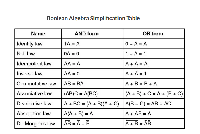
The basic laws of logical algebra include:
- Identity Laws:
- Identity Law for OR: A + 0 = A, A + 1 = 1
- Identity Law for AND: A · 1 = A, A · 0 = 0
- Null Laws:
- Null Law for OR: A + A’ = 1, A + A = A
- Null Law for AND: A · A’ = 0, A · A = A
- Domination Laws:
- Domination Law for OR: A + A’ = 1
- Domination Law for AND: A · A’ = 0
- Idempotent Laws:
- Idempotent Law for OR: A + A = A
- Idempotent Law for AND: A · A = A
- Inverse Laws (Complement Law):
- Inverse Law for OR: A + A’ = 1
- Inverse Law for AND: A · A’ = 0
- Commutative Laws:
- Commutative Law for OR: A + B = B + A
- Commutative Law for AND: A · B = B · A
- Associative Laws:
- Associative Law for OR: (A + B) + C = A + (B + C)
- Associative Law for AND: (A · B) · C = A · (B · C)
- Distributive Laws:
- Distributive Law of AND over OR: A · (B + C) = (A · B) + (A · C)
- Distributive Law of OR over AND: A + (B · C) = (A + B) · (A + C)
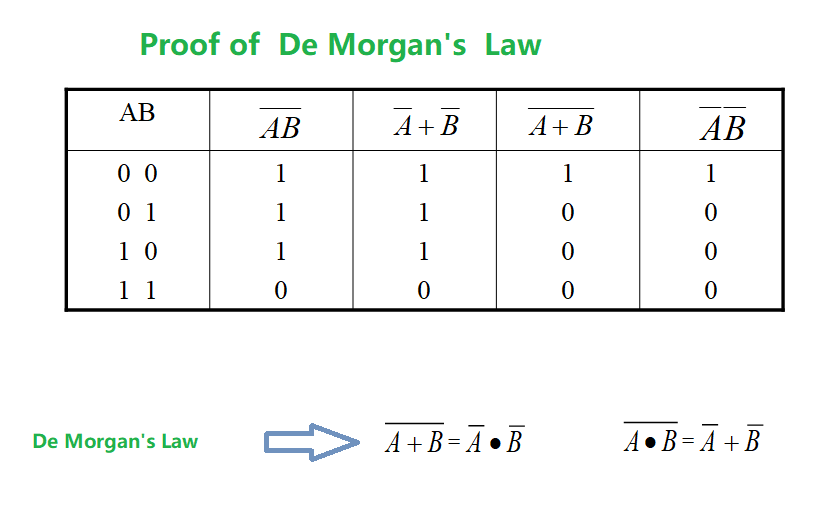
- De Morgan’s Laws:
- De Morgan’s Law for OR: (A + B)’ = A’ · B’
- De Morgan’s Law for AND: (A · B)’ = A’ + B’
These basic laws provide rules and relationships for manipulating and simplifying logical expressions in logical algebra.
Note:
- The Null Law, also known as the 0-1 Law or Law of Null
- Law of Identity, also known as the Identity Law or Reflexive Law, states that any proposition A is logically equivalent to itself.
- Idempotent Law, also known as the Law of Idempotence, states that applying a logical operation (AND or OR) to a proposition with itself produces the same proposition as the result.
- The Complement Law, also known as Inverse Laws, states that for any proposition A, there exists a complementary proposition A’ (not A) such that A + A’ = 1 and A · A’ = 0. The complement of A represents the opposite value of A. It can also be understood as the logical negation or inversion of the proposition.
2.2) The Relationship Between Variables and Constants
- Variables: Variables in boolean algebra represent unknown or changing values. They are denoted by symbols such as A, B, C, x, y, z, etc. Variables can take on two possible values: logic 0 and logic 1. The values of variables can change based on the conditions or inputs in logical expressions.
- Constants: Constants in logical algebra represent fixed or predetermined values. They are also represented by logic 0 and logic 1. Constants do not change their values throughout the logical expression or calculation. They can be used as inputs or conditions in logical operations.
Variables and constants work together in logical algebra to form logical expressions and determine the results or outcomes based on their values. The relationship between variables and constants is essential in defining logical functions and describing the behavior of logical systems.
The Null Law, Law of Identity, Law of Idempotence, and Complement Law are all relationship expressions related to variables and constants. Since logical constants only have two possible values, 0 and 1, the results of operations between logical variables and constants can be directly inferred based on the definitions of the three basic logical operations. These laws are also referred to as axioms and can be used to prove other formulas.
2.3) The Laws Similar to Ordinary Algebra
The laws similar to ordinary algebra include:
- Associative Law: Regardless of how the parentheses are arranged, the result of an operation remains the same. For example, in logical AND operation, (A ∧ B) ∧ C = A ∧ (B ∧ C).
- Distributive Law: Operations can be distributed among multiple operations. For example, in the logical AND and OR operations, A ∧ (B ∨ C) = (A ∧ B) ∨ (A ∧ C).
- Absorption Law: Performing the same operation on a variable does not change its result. For example, in logical AND operation, A ∧ A = A.
- Duality Law: Replacing logical AND (AND) with logical OR (OR), and logical constants 0 and 1 with each other, in a logical expression results in a new expression with the same logical meaning. For example, in logical AND operation, A ∧ B = ¬(¬A ∨ ¬B).
These laws and rules apply to both logical algebra and ordinary algebra, demonstrating their similarity and consistency.
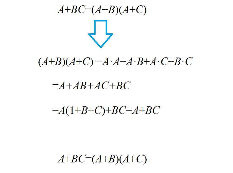
Following Formula is not correct in ordinary Algebra:
A+BC=(A+B)(A+C)
But it is correct in Boolean Algebra.
2.4) Special Laws in Boolean Algebra
The laws of inversion and reduction are special laws in logical algebra. The law of inversion, also known as De Morgan’s theorem, plays a particularly important role in logical algebra. It provides a method for transforming logical expressions by converting the complement of logical AND into logical OR and the complement of logical OR into logical AND. The correctness of the law of inversion can be demonstrated through the truth table.
3. Three Important Rules
3.1) Substitution Rule
The Substitution Rule is an important rule in Boolean algebra. It allows for the substitution of equivalent subexpressions for variables or constants in a logical expression without changing the result of the expression.
According to the Substitution Rule, if there is a logical expression E that contains variables or constants, and these variables or constants can be replaced by equivalent logical expressions F, then substituting F for these variables or constants in E will not change the overall result of the expression.
The application of the Substitution Rule can simplify logical expressions, prove equivalences, and facilitate logical reasoning. By selecting appropriate equivalent subexpressions for substitution, complex logical expressions can be simplified in Boolean algebra, making them easier to understand and manipulate.
The Substitution Rule states that for any logical equation, if we replace a variable appearing on both sides of the equation with the same logical function, the equation remains true. This rule is known as the Substitution Rule.
Since logical functions, like logical variables, have only two possible values (0 and 1), the correctness of the Substitution Rule is straightforward to understand. By applying the Substitution Rule, we can extend the application scope of basic laws in logic algebra.
IF F (M(X,Y,Z), B, C…) = G (M(X,Y,Z), B, C …)
F, G, M are functions
IF A = M(X,Y,Z)
F(A,B,C … ) = G(A,B,C …)
is correct
3.1.1 ) Example
A + B = A·B (The Inversion Law)
If we use F = B + C to substitute B in above equation
we can get following equation:
A+B+C=A+F=A·B+C=A·B·C
3.2) Inversion Rule
For any logical function F, if we replace all the operators “·” with “+”, “+” with “·”, constant “0” with “1”, “1” with “0”, original variables with their complements, and complemented variables with their originals, the resulting expression is called the complement or inverse function of the original function F.
The inversion rule is an extension of the De Morgan’s theorem, and it can be used to conveniently derive the complement or inverse function of a given function.
For example:
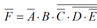
IF F=AB+C·D+AC
Then:
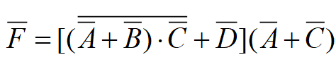
IF
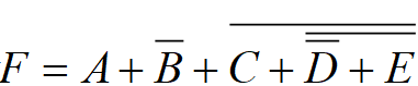
Then
When applying the inversion rule, two points should be noted:
- The order of operations in the original expression should not be altered. Evaluate the operations within parentheses first, and then follow the “AND before OR” principle.
- The negation (NOT) operator that does not apply to a single variable should be left unchanged.
3.3) Dual Rule
The duality rule in logic algebra states that for any logical expression, if we interchange the AND and OR operators, replace 0 with 1 and 1 with 0, and negate all variables, the resulting expression is the dual of the original expression. The dual rule is a fundamental property that allows us to obtain the dual expression of a given logic function.
For any logic function F, if we replace all the AND operators (·) with OR operators (+), replace all the OR operators (+) with AND operators (·), replace all the constants 0 with 1, replace all the constants 1 with 0, and keep the variables unchanged, we obtain the dual expression of F, denoted as F’ (or F*).
The dual expression represents the logical complement of the original function F.
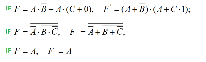
In each of the examples mentioned above, F’ is the dual expression of F. It can be easily proven that F is also the dual expression of F’. In other words, F and F’ are dual expressions of each other.
Every logical function has a dual expression. If the original equation holds true, then the dual equation will also hold true. This logical reasoning is called the principle of duality or the duality rule. It is important to note that when deriving the dual expression from the original expression, the order of operations should not be changed, and the negation symbols should remain unchanged.
By observing the earlier basic laws and formulas of logic algebra, it is evident that they all appear in pairs and are dual expressions of each other. For example, if the distributive law of multiplication over addition holds true, i.e., A(B+C) = AB+AC, then according to the duality rule, A+BC = (A+B)(A+C), which means the distributive law of addition over multiplication also holds true.