Introduction
An encoder is a combinational logic circuit that converts information from multiple input signals into a compact binary code.
In a conventional binary encoder, one active input is translated into a binary number identifying that input.
Encoders are fundamental building blocks of digital electronics.
They are used in CPUs, microcontrollers, FPGAs, ASICs, communication systems, and digital control circuits.
For example, an 8-to-3 encoder converts one of eight active input signals into a three-bit binary output.
Encoders help reduce the number of signals required to represent information and are often used together with decoders in digital systems.
How Does an Encoder Work?
A conventional binary encoder receives multiple input signals and generates a binary code corresponding to the active input.
For an encoder with 2ⁿ inputs, n output bits are sufficient to identify each input.
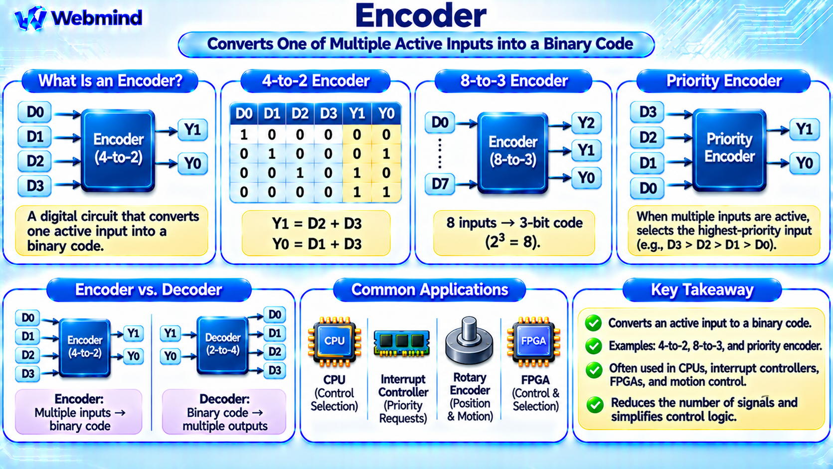
For example, a 4-to-2 encoder has four inputs, D0 through D3, and two outputs, Y1 and Y0.
When D0 is active, the output is 00. When D1 is active, the output is 01. When D2 is active, the output is 10. When D3 is active, the output is 11.
A basic encoder normally assumes that only one input is active at a time.
If multiple inputs become active simultaneously, a conventional encoder may produce an ambiguous or invalid result.
Priority encoders are designed to handle this situation.
What Is a 4-to-2 Encoder?
A 4-to-2 encoder converts four possible input signals into a two-bit binary code.
Assuming active-high inputs and exactly one active input, its operation is:
D0 = 1 → Y1Y0 = 00
D1 = 1 → Y1Y0 = 01
D2 = 1 → Y1Y0 = 10
D3 = 1 → Y1Y0 = 11
The corresponding Boolean expressions are:
Y1 = D2 OR D3
Y0 = D1 OR D3
These equations can be implemented using two OR gates.
Notice that the output 00 can also appear when no input is active.
Therefore, practical encoders may include a Valid signal indicating whether an input has been detected.
What Is an 8-to-3 Encoder?
An 8-to-3 encoder converts eight possible input signals into a three-bit binary output.
The input signals are commonly labeled D0 through D7, while the outputs are Y2, Y1, and Y0.
For example:
D0 active → 000
D1 active → 001
D2 active → 010
D3 active → 011
D4 active → 100
D5 active → 101
D6 active → 110
D7 active → 111
This arrangement reduces eight possible input selections to a three-bit binary representation.
The encoder is especially useful when hardware must communicate which one of several signals is active.
What Is a Priority Encoder?
A priority encoder is a special type of encoder that handles situations where more than one input is active simultaneously.
Instead of producing an ambiguous result, it selects the active input with the highest assigned priority.
For example, consider a 4-to-2 priority encoder in which D3 has the highest priority and D0 has the lowest.
If D1 and D3 are both active, the encoder produces the binary code 11, corresponding to D3.
If D0 and D2 are active, the output is 10, corresponding to D2.
Priority encoders are widely used in interrupt controllers, arbitration circuits, and digital control systems.
They allow hardware to identify which request should receive attention first.
How Is an Encoder Built from Logic Gates?
A simple binary encoder can be constructed using OR gates.
For example, a 4-to-2 encoder uses the Boolean expressions:
Y1 = D2 + D3
Y0 = D1 + D3
Here, the plus symbol represents logical OR.
For a basic encoder, these equations produce the correct output when exactly one input is active.
A priority encoder requires additional logic to determine which active input has precedence.
It may use AND, OR, and NOT gates, or more complex optimized CMOS structures.
Modern EDA tools can synthesize encoder functions into standard logic cells or FPGA LUTs.
Encoder vs. Decoder: What Is the Difference?
Encoders and decoders perform opposite types of logical transformations.
Encoder: Converts one of several active input signals into a binary code.
Decoder: Converts a binary input code into one of several selected output signals.
For example, an 8-to-3 encoder converts eight possible input selections into a three-bit code.
A 3-to-8 decoder converts a three-bit binary code into eight possible selected outputs.
Encoders reduce the number of signals required to represent a selection, while decoders expand a binary code into individual control signals.
Both are important components of digital communication and control systems.
Encoder vs. Multiplexer
An encoder and a multiplexer are different digital circuits.
A multiplexer selects one of several data inputs and forwards its value to a single output.
An encoder identifies which input signal is active and produces a binary code representing that input.
For example, a 4-to-1 multiplexer uses two select bits to choose one of four data inputs.
A 4-to-2 encoder instead receives four input signals and generates a two-bit code.
A multiplexer forwards selected data, while an encoder converts an active input position into a binary representation.
Encoders in CPUs and Interrupt Controllers
Encoders are important in processor control logic.
A CPU may receive requests from several hardware components. An interrupt controller must determine which eligible interrupt should be handled.
Priority selection logic, which can include priority encoders, helps identify the highest-priority active request.
Encoders may also be used in register selection, instruction processing, arbitration, and resource management.
However, modern interrupt controllers often include additional mechanisms such as masking, programmable priorities, interrupt routing, and request tracking.
A priority encoder is only one possible component of these more complex systems.
Encoders in FPGAs
FPGAs can implement encoder circuits using configurable logic resources.
For example, a 4-to-2 priority encoder can be described using Verilog or VHDL.
An EDA synthesis tool converts the hardware description into appropriate LUTs and routing resources.
Encoders are used in FPGA-based control systems, interrupt handling, bus arbitration, and digital communication interfaces.
Because FPGAs are reconfigurable, the number of inputs and priority rules can be modified by changing the hardware design.
This makes encoders useful in many programmable digital systems.
How Is an Encoder Described in Verilog?
Verilog provides several ways to describe encoder logic.
A simple encoder can be implemented using Boolean expressions or a combinational case statement.
A priority encoder is often described using an ordered sequence of if and else if conditions.
For example, the hardware description can test D3 first, followed by D2, D1, and D0.
When multiple inputs are active, the first satisfied condition determines the output.
During synthesis, the EDA tool converts this behavior into logic gates or FPGA resources.
Designers should also specify what happens when no input is active, commonly using an additional Valid output.
What Is a Rotary Encoder?
The term encoder is also used for devices that convert physical movement into electrical signals.
A rotary encoder measures rotational position or movement.
For example, an incremental rotary encoder may generate two digital signals, commonly labeled A and B, whose transitions are offset in phase.
These signals allow a microcontroller to determine rotational direction and count movement increments.
An absolute rotary encoder provides a digital code representing a particular shaft position.
Although rotary encoders and binary logic encoders share the general idea of converting information into coded signals, their physical operation and applications are different.
Rotary encoders are widely used in robotics, motor control, industrial automation, and measurement systems.
What Is an Encoder in Communication Systems?
In digital communication, the term encoder can also describe a circuit or algorithm that converts information into a specific representation for transmission or storage.
For example, a line encoder converts binary data into electrical signaling patterns suitable for a communication channel.
An error-correcting encoder adds structured redundancy that allows a receiver to detect or correct certain data errors.
These functions are more complex than a basic combinational binary encoder.
The meaning of the word encoder therefore depends on context.
In digital logic, it commonly refers to a circuit that converts active input selections into binary codes.
What Is Propagation Delay in an Encoder?
Like other digital logic circuits, an encoder requires time to respond to changes in its inputs.
Propagation delay is the interval between an input transition and the corresponding output transition.
The delay depends on the number of logic stages, transistor characteristics, output load, and circuit implementation.
Priority encoders may require more complex logic than simple encoders, potentially increasing delay.
In high-speed digital systems, encoder timing can influence interrupt response, arbitration, and control signal generation.
Engineers use timing analysis to ensure that encoder outputs meet the required timing constraints.
Advantages of Encoder Circuits
Reduced Signal Count: Multiple input selections can be represented using fewer binary output bits.
Efficient Control Logic: Encoders simplify the representation of device requests and selection signals.
Priority Handling: Priority encoders can select the most important active request.
Scalability: Larger encoders can be constructed using hierarchical logic structures.
Flexible Implementation: Encoders can be implemented using logic gates, ASIC standard cells, or FPGA LUTs.
These advantages make encoders important components in digital hardware design.
Limitations of Encoder Circuits
Encoders also have several limitations.
Multiple Active Inputs: A basic encoder may produce an ambiguous result when several inputs are active.
No-Input Condition: A separate Valid signal may be needed to distinguish an inactive encoder from a valid zero code.
Propagation Delay: Large encoders and priority networks may introduce significant timing delays.
Power Consumption: Switching activity consumes electrical power.
Design Complexity: Priority encoders require additional logic to enforce the required ordering of input requests.
These limitations can be addressed through priority logic, valid indicators, hierarchical designs, and timing optimization.
Where Are Encoders Used?
Encoders are found in many digital electronic systems.
CPUs: Control logic, resource selection, and priority processing.
Interrupt Controllers: Identify active interrupt requests according to priority rules.
Microcontrollers: Process digital input selections and signals from external encoding devices.
FPGAs: Implement configurable priority logic and control circuits.
ASICs: Provide specialized encoding, arbitration, and communication functions.
Communication Systems: Convert information into suitable digital codes.
Robotics and Industrial Systems: Use rotary and position encoders for motion measurement and control.
Understanding encoders helps explain how digital hardware represents and selects information efficiently.
Conclusion
An encoder is a digital logic circuit that converts one of multiple active input signals into a binary code.
Common binary encoders include 4-to-2 and 8-to-3 configurations, while priority encoders handle situations where several inputs are active simultaneously.
Encoders can be implemented using Boolean logic gates, CMOS circuits, or configurable FPGA resources.
They are widely used in interrupt controllers, processor control logic, communication systems, and digital hardware.
Understanding encoders provides an important foundation for studying Boolean algebra, decoders, multiplexers, priority circuits, CPU architecture, Verilog, FPGA development, and digital integrated circuit design.