Introduction
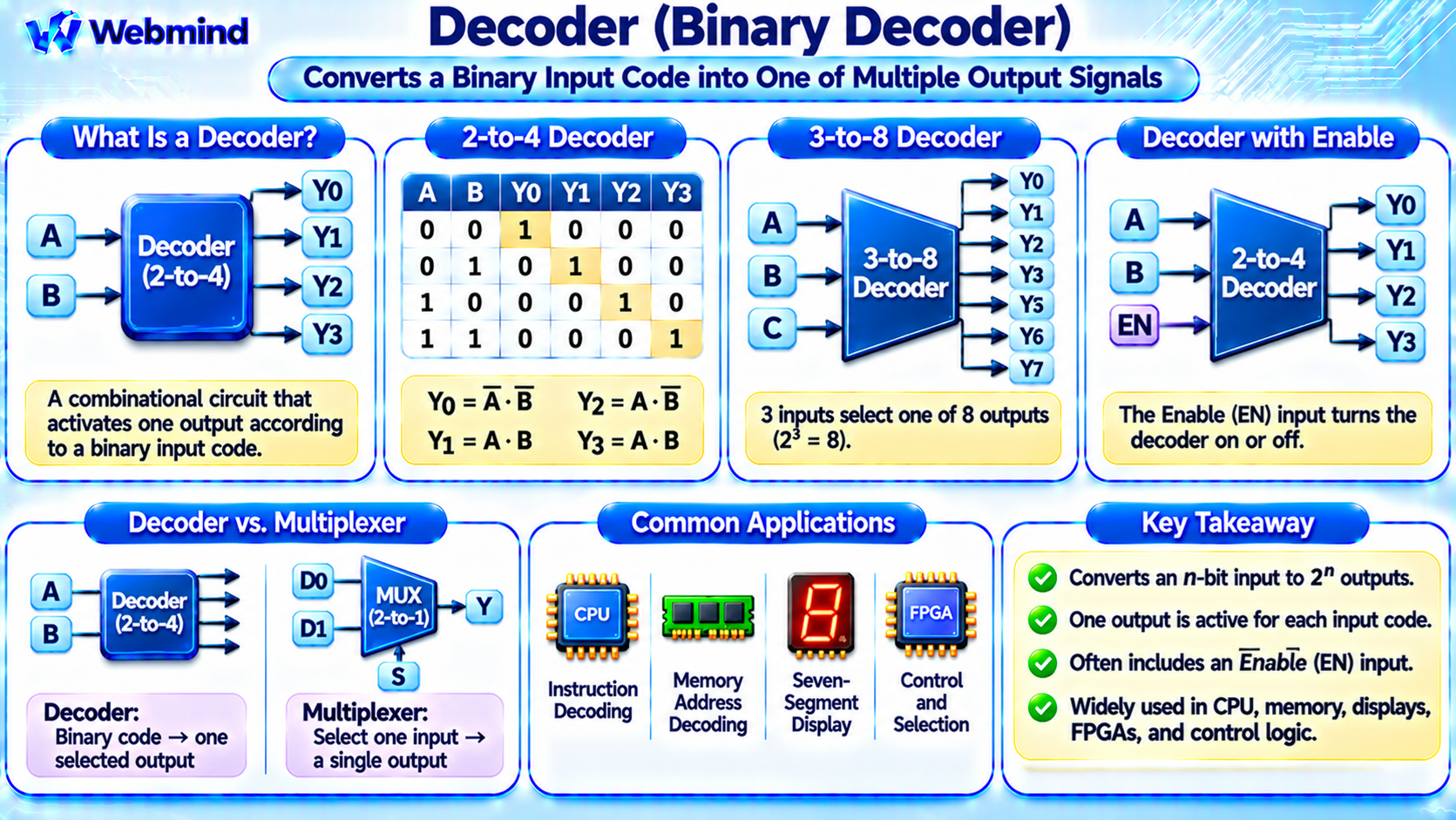
A decoder is a combinational logic circuit that converts a binary input code into a set of output signals.
In a conventional binary decoder, each input combination activates one corresponding output, allowing digital systems to identify or select specific devices, memory locations, and hardware functions.
Decoders are fundamental components of digital electronics. They are widely used in CPUs, memory systems, microcontrollers, FPGAs, ASICs, and communication hardware.
For example, a memory address decoder can determine which memory device or region should respond to a particular address.
Decoders are also used in instruction processing, register selection, and digital control systems.
How Does a Decoder Work?
A binary decoder receives a group of binary input signals and generates outputs according to the input combination.
A conventional n-to-2ⁿ decoder has n input bits and up to 2ⁿ distinct decoded outputs.
For example, a 2-to-4 decoder has two inputs, A and B, and four outputs, Y0 through Y3.
When the inputs are 00, output Y0 is selected. When the inputs are 01, Y1 is selected. Inputs 10 select Y2, while inputs 11 select Y3.
In an active-high decoder, the selected output becomes 1 while the other outputs remain 0.
Some decoders use active-low outputs, meaning the selected output becomes 0 instead. The exact behavior depends on the circuit design.
What Is a 2-to-4 Decoder?
A 2-to-4 decoder is one of the simplest binary decoder circuits.
It contains two input signals and four output signals.
Its operation can be described as follows:
A B = 00 → Y0 = 1
A B = 01 → Y1 = 1
A B = 10 → Y2 = 1
A B = 11 → Y3 = 1
For each combination, only one output is active in a conventional active-high decoder.
The Boolean expressions are:
Y0 = A’ · B’
Y1 = A’ · B
Y2 = A · B’
Y3 = A · B
Here, the apostrophe represents NOT, and the dot represents AND.
These equations show how the decoder can be implemented using basic logic gates.
What Is a 3-to-8 Decoder?
A 3-to-8 decoder receives three binary inputs and produces eight decoded outputs.
The three input bits represent binary values from 000 through 111.
Each possible combination selects one corresponding output.
For example, input 000 selects Y0, input 011 selects Y3, and input 111 selects Y7.
A 3-to-8 decoder is useful when a digital system needs to select one of eight devices, registers, or control signals.
Larger decoders can be constructed by combining smaller decoder circuits.
A 4-to-16 decoder, for example, uses four input bits to select one of sixteen outputs.
How Is a Decoder Built from Logic Gates?
A binary decoder can be implemented using AND and NOT gates.
Consider a 2-to-4 decoder.
The input signals A and B are connected to inverter circuits to generate their complements, A’ and B’.
Four AND gates then implement the Boolean expressions for Y0 through Y3.
For example, Y0 becomes 1 when both A and B are 0, because A’ and B’ are both 1.
Similarly, Y3 becomes 1 only when A and B are both 1.
Modern integrated circuits may use NAND, NOR, or optimized CMOS structures to implement the same functions.
The implementation depends on timing requirements, circuit area, power consumption, and the available standard-cell library.
What Is an Enable Input?
Many decoder circuits include an additional control input called Enable, commonly labeled EN or E.
The enable signal determines whether the decoder is active.
For a conventional active-high enable input, EN = 1 allows the decoder to operate normally.
When EN = 0, all active-high decoded outputs remain inactive.
Enable inputs allow multiple decoders to work together in larger systems.
For example, a processor can use one decoder to select a memory region and another decoder to select a device within that region.
Some commercial decoder ICs use active-low enable inputs or multiple enable signals.
Decoder vs. Encoder: What Is the Difference?
A decoder and an encoder perform different logical functions.
Decoder: Converts an n-bit binary code into one of up to 2ⁿ selected output signals.
Encoder: Converts a set of input signals into a binary code representing the selected input.
For example, a 2-to-4 decoder converts two input bits into four possible selected outputs.
A conventional 4-to-2 encoder performs the reverse type of operation, converting one of four active inputs into a two-bit binary code.
Basic encoders generally assume that only one input is active at a time.
Priority encoders extend this concept by resolving situations where multiple inputs are active.
Both encoders and decoders are important in digital control and communication systems.
Decoder vs. Multiplexer
Decoders and multiplexers are closely related but serve different purposes.
A multiplexer, or MUX, selects one of several data inputs and forwards it to a single output.
A decoder uses a binary input code to activate a corresponding output signal.
For example, a 4-to-1 multiplexer selects one of four data inputs using two select bits.
A 2-to-4 decoder uses two input bits to activate one of four output lines.
Decoders can also be used as components within multiplexer implementations because decoded select signals can control which data path is enabled.
What Is a Memory Address Decoder?
Memory address decoding is one of the most important applications of decoder circuits.
A CPU generates memory addresses when reading or writing data.
The memory system must determine which memory device or address region should respond.
Address decoding logic examines selected address bits and generates the required control signals.
For example, a simple embedded system may contain RAM, ROM, and memory-mapped peripheral registers.
The address decoder determines which component should receive a particular memory access.
In modern processors, memory addressing involves additional mechanisms such as caches, address translation, and memory controllers.
Nevertheless, decoding remains essential for selecting the appropriate hardware resources.
How Are Decoders Used in CPUs?
CPUs use decoding logic in several functional areas.
Instruction Decoding: Identifies machine instruction fields and helps generate control signals for executing operations.
Register Selection: Determines which registers are selected for reading or writing.
Memory Address Decoding: Helps identify memory regions and hardware devices.
Control Signal Generation: Activates specific internal operations based on processor state and instruction information.
Functional Unit Selection: Helps direct operations toward appropriate processing resources.
Modern instruction decoders are much more complex than simple n-to-2ⁿ binary decoders.
They may combine Boolean logic, lookup structures, programmable logic, and microcode.
However, the fundamental principle remains the same: interpreting an input code to determine the required operation.
What Is a Seven-Segment Decoder?
A seven-segment decoder converts a binary or coded numerical input into signals used to control a seven-segment display.
A seven-segment display contains seven independently controlled segments, commonly labeled a through g.
Different combinations of illuminated segments form numerical digits.
For example, displaying the number 0 requires six outer segments, while the middle segment remains off.
A Binary-Coded Decimal (BCD) to seven-segment decoder accepts a four-bit input representing decimal digits from 0 through 9.
It generates the required segment-control outputs.
The precise output logic depends on whether the display uses common-anode or common-cathode connections and on the decoder’s electrical interface.
Seven-segment decoders are widely used in digital clocks, counters, instruments, and educational electronics.
Decoders in FPGAs
An FPGA, or Field-Programmable Gate Array, can implement decoder functions using configurable logic resources.
For example, a 3-to-8 decoder can be described in Verilog and synthesized into FPGA logic.
The synthesis tool maps the decoder onto suitable Look-Up Tables (LUTs) and other available resources.
Each decoded output represents a Boolean function of the input bits.
FPGA decoders are commonly used for address selection, control signal generation, peripheral interfaces, and register access.
Because FPGA logic is configurable, the decoder’s behavior can be modified by changing the hardware design and regenerating the configuration bitstream.
How Is a Decoder Described in Verilog?
Hardware Description Languages such as Verilog provide convenient ways to describe decoder behavior.
For example, a 2-to-4 decoder can be represented using a combinational case statement.
The statement examines a two-bit input and assigns one of four output patterns.
A decoder can also be described using Boolean expressions or shift operations.
During synthesis, an EDA tool converts the description into the logic resources required by the target device.
For an ASIC, the decoder may be implemented using standard-cell gates.
For an FPGA, it may be implemented using LUTs and programmable routing resources.
Verification should confirm that every input combination produces the intended output.
What Is Propagation Delay in a Decoder?
A decoder is a physical electronic circuit, so its outputs do not respond instantaneously to input changes.
Propagation delay is the time required for a change in an input or enable signal to affect the output.
Larger decoders may require additional logic stages, increasing the delay.
In high-speed systems, decoder timing can influence memory access, register selection, and control signal generation.
Transient output glitches may also occur when multiple input bits change at slightly different times.
Engineers use timing analysis and appropriate synchronization techniques to ensure reliable circuit operation.
Advantages of Decoder Circuits
Simple Binary Selection: A small number of input bits can select one of many output signals.
Efficient Control Logic: Decoders reduce the need for separate control signals for every device or function.
Scalability: Larger decoders can be constructed using smaller logic blocks.
Flexible Implementation: Decoder functions can be implemented using gates, CMOS circuits, or FPGA LUTs.
Wide Application Range: Decoders are useful in processors, memory systems, displays, and digital controllers.
These characteristics make decoders fundamental building blocks of digital systems.
Limitations of Decoder Circuits
Decoders also introduce several design considerations.
Increasing Complexity: The number of outputs grows exponentially with the number of input bits in a conventional full binary decoder.
Propagation Delay: Larger decoder circuits may contain additional logic stages.
Power Consumption: Switching activity consumes dynamic power.
Output Fanout: Decoder outputs may require buffers when driving many circuit inputs.
Glitches: Unsynchronized input changes can cause brief unintended output transitions.
These limitations can be managed through hierarchical decoding, buffering, timing analysis, and careful circuit design.
Where Are Decoders Used?
Decoders are widely used throughout digital electronic systems.
CPUs: Instruction decoding, register selection, and control signal generation.
Memory Systems: Address decoding and memory device selection.
Microcontrollers: Peripheral selection and memory-mapped I/O control.
FPGAs: Configurable address decoders and digital control logic.
ASICs: Specialized selection circuits and hardware controllers.
Digital Displays: BCD-to-seven-segment conversion.
Communication Systems: Channel identification and control signal decoding.
Their ability to convert binary codes into specific selections makes decoders essential in modern digital hardware.
Conclusion
A decoder is a combinational logic circuit that converts a binary input code into a corresponding set of output signals.
Common binary decoders include 2-to-4, 3-to-8, and 4-to-16 configurations.
Decoders can be built using Boolean logic gates and are widely used for memory addressing, instruction decoding, register selection, and display control.
In FPGAs, decoder functions are implemented using configurable logic resources such as LUTs, while ASICs use transistor-based logic circuits.
Understanding decoders provides an important foundation for studying Boolean algebra, logic gates, multiplexers, memory systems, CPU architecture, Verilog, FPGA design, and digital integrated circuits.