Introduction
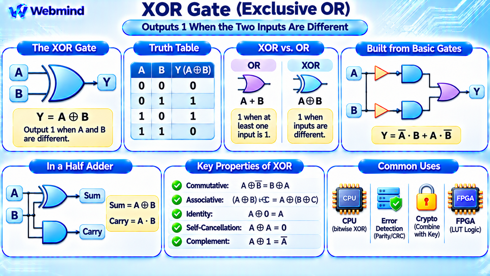
An XOR gate, or Exclusive OR gate, is a digital logic gate that produces an output of 1 when its two binary inputs are different.
When both inputs have the same value, the output is 0.
XOR is one of the fundamental operations in Boolean algebra and digital electronics.
It is widely used in CPUs, microcontrollers, FPGAs, ASICs, arithmetic circuits, error detection, and digital communication systems.
Unlike a standard OR gate, which produces 1 when at least one input is 1, a two-input XOR gate produces 1 only when exactly one input is 1.
XOR is especially important because it forms the basis of binary addition and many other digital operations.
How Does an XOR Gate Work?
An XOR gate receives two binary inputs, commonly labeled A and B, and produces one output, Y.
Its Boolean expression is:
Y = A XOR B
The XOR operation is also represented by the symbol ⊕.
Y = A ⊕ B
The output depends on whether the inputs are equal or different.
If A = 0 and B = 0, the output is 0. If A = 0 and B = 1, the output is 1. If A = 1 and B = 0, the output is 1. If A = 1 and B = 1, the output is 0.
Therefore, an XOR gate can be understood as a circuit that detects whether two binary inputs are different.
XOR Truth Table
A truth table shows every possible input combination and its corresponding output.
For a two-input XOR gate, there are four possible combinations.
A = 0, B = 0 → Y = 0
A = 0, B = 1 → Y = 1
A = 1, B = 0 → Y = 1
A = 1, B = 1 → Y = 0
The output is 1 only when the input values differ.
This truth table defines the logical behavior of a two-input XOR gate, regardless of how the circuit is physically implemented.
XOR vs. OR: What Is the Difference?
XOR and OR are closely related Boolean operations, but their behavior differs when both inputs are 1.
An OR gate produces 1 whenever at least one input is 1.
An XOR gate produces 1 only when the two inputs are different.
For example, when A = 1 and B = 1:
A OR B = 1
A XOR B = 0
This difference is important in digital circuit design.
An OR gate is useful when any one of several conditions can activate an output. An XOR gate is useful when a circuit needs to identify unequal inputs or perform binary arithmetic.
How Is XOR Expressed in Boolean Algebra?
An XOR function can be constructed using basic AND, OR, and NOT operations.
The Boolean expression is:
Y = A’ · B + A · B’
Here, A’ means NOT A, B’ means NOT B, the dot represents AND, and the plus sign represents OR.
The first term, A’ · B, becomes 1 when A = 0 and B = 1.
The second term, A · B’, becomes 1 when A = 1 and B = 0.
Combining these terms with OR produces the XOR function.
This demonstrates that XOR is not an entirely separate mathematical system. It can be implemented using combinations of basic Boolean operations.
How Is an XOR Gate Built from Transistors?
Modern XOR gates are commonly implemented using CMOS technology, which combines NMOS and PMOS transistors.
A conventional static CMOS XOR circuit can be constructed using complementary transistor networks that implement the required Boolean function.
Other implementations use transmission gates, pass-transistor logic, or specialized standard-cell structures.
The number of transistors depends on the circuit architecture and design requirements.
Circuit designers select an implementation based on propagation delay, power consumption, transistor count, output drive strength, and manufacturing technology.
Although the internal transistor arrangements vary, every correctly implemented two-input XOR gate follows the same truth table.
XOR in Binary Addition
One of the most important applications of XOR is binary arithmetic.
A half adder is a digital circuit that adds two binary digits, A and B.
It produces two outputs: Sum and Carry.
The Sum output is calculated using XOR:
Sum = A XOR B
The Carry output is calculated using AND:
Carry = A AND B
For example, when A = 1 and B = 1, the Sum output is 0 and the Carry output is 1.
Together, these outputs represent binary 10, which equals decimal 2.
A full adder extends this principle by including a carry input.
For a full adder:
Sum = A XOR B XOR Cin
The carry output can be expressed as:
Cout = A · B + Cin · (A XOR B)
Full adders are combined into larger arithmetic circuits used inside processors.
XOR in CPUs and ALUs
The Arithmetic Logic Unit (ALU) is responsible for performing arithmetic and logical operations inside a CPU.
XOR gates are important components of ALU circuits.
They are used in binary addition, bitwise logical operations, comparisons, and selected arithmetic implementations.
For example, a CPU may provide a bitwise XOR instruction.
Consider two four-bit values:
A = 1010
B = 1100
Applying XOR to each corresponding pair of bits produces:
Y = 0110
Bitwise XOR operates independently on each bit position.
This operation is useful in low-level programming, bit manipulation, data processing, and many hardware algorithms.
XOR and XNOR: What Is the Difference?
XNOR stands for Exclusive NOR and is the logical inverse of XOR.
An XOR gate produces 1 when two inputs are different.
An XNOR gate produces 1 when two inputs are equal.
For example:
0 XOR 0 = 0
0 XNOR 0 = 1
1 XOR 0 = 1
1 XNOR 0 = 0
The XNOR function can be written as:
Y = NOT (A XOR B)
XNOR is useful in equality comparison circuits, while XOR is useful for detecting differences.
Both operations are widely used in digital logic systems.
XOR in Error Detection
XOR is commonly used in digital communication and data integrity systems.
One important application is parity checking.
A parity bit is an additional bit used to detect certain transmission or storage errors.
For example, even parity requires the total number of 1 bits, including the parity bit, to be even.
XOR can calculate the parity of a group of binary values.
For three data bits:
P = A XOR B XOR C
If the data contains an odd number of ones, P = 1. If it contains an even number of ones, P = 0.
Adding this parity bit produces an even total number of ones.
A simple parity check can detect any odd number of bit errors, but it cannot detect every possible error pattern.
More advanced error-detection techniques, including Cyclic Redundancy Checks (CRCs), also use XOR operations as part of their binary polynomial calculations.
XOR in Cryptography
XOR is widely used in cryptographic algorithms because it is simple, efficient, and reversible when one operand is known.
Consider the expression:
C = P XOR K
Here, P represents plaintext data, K represents a key or keystream, and C represents the resulting ciphertext.
Applying the same keystream again recovers the original data:
P = C XOR K
This works because:
A XOR B XOR B = A
However, XOR alone does not provide secure encryption.
Cryptographic security depends on how keys and keystreams are generated, protected, and used.
For example, stream ciphers use XOR together with carefully designed cryptographic keystream generation.
XOR is also an important internal operation in many block ciphers and cryptographic hash functions.
XOR in FPGAs and LUTs
An FPGA, or Field-Programmable Gate Array, uses configurable hardware resources to implement digital logic functions.
Modern FPGAs commonly use Look-Up Tables (LUTs) to implement combinational logic.
A two-input XOR function has four truth-table outputs:
0, 1, 1, 0
A suitable LUT can store these four values and select the correct output based on inputs A and B.
The same LUT can be reconfigured to implement AND, OR, NAND, NOR, or another Boolean function.
This demonstrates how FPGA hardware can implement XOR without requiring a separate, fixed XOR gate for every logical operation.
Some FPGAs also provide dedicated carry-chain resources for efficient arithmetic operations involving XOR and other logic.
XOR in Verilog
Hardware Description Languages such as Verilog allow engineers to describe XOR functions directly.
In Verilog, the caret symbol represents bitwise XOR.
For example, the expression assign y = a ^ b; describes a bitwise XOR operation between signals a and b.
When a and b are single-bit signals, this implements the standard two-input XOR function.
When they are vectors, XOR operates on corresponding bits, subject to Verilog’s expression sizing rules.
During synthesis, an EDA tool converts the operation into logic gates, standard cells, or FPGA resources.
This makes XOR easy to use in digital hardware design.
Important Properties of XOR
XOR has several mathematical properties that make it useful in digital systems.
Commutative Property: A XOR B = B XOR A.
Associative Property: (A XOR B) XOR C = A XOR (B XOR C).
Identity Property: A XOR 0 = A.
Self-Cancellation Property: A XOR A = 0.
Complement Property: A XOR 1 = NOT A, for a single Boolean bit.
Reversibility: (A XOR B) XOR B = A.
These properties are useful in arithmetic circuits, parity generation, cryptographic operations, and software algorithms.
Where Are XOR Gates Used?
XOR gates are important in many areas of digital electronics.
CPUs: Implement arithmetic operations, bitwise instructions, and logic functions.
Microcontrollers: Perform binary calculations, comparisons, and bit manipulation.
FPGAs: Implement configurable Boolean functions, arithmetic circuits, and digital signal processing logic.
ASICs: Support specialized arithmetic, communication, and control circuits.
Error Detection: Generate parity bits and support CRC calculations.
Cryptography: Combine binary data with keys and perform internal algorithm operations.
Digital Communications: Support coding, decoding, scrambling, and data-processing circuits.
XOR is therefore one of the most versatile operations in digital logic.
Conclusion
An XOR gate is a digital logic gate that produces 1 when its two inputs are different and 0 when they are equal.
Its Boolean operation can be expressed as A XOR B or A ⊕ B.
XOR is essential for binary addition, arithmetic circuits, bitwise CPU instructions, parity checking, and many cryptographic algorithms.
In modern semiconductor hardware, XOR functions are implemented using transistor-based CMOS circuits or configurable FPGA LUTs.
Understanding XOR provides an important foundation for studying Boolean algebra, truth tables, logic gates, binary arithmetic, CPU architecture, Verilog programming, FPGA development, and digital circuit design.