Introduction
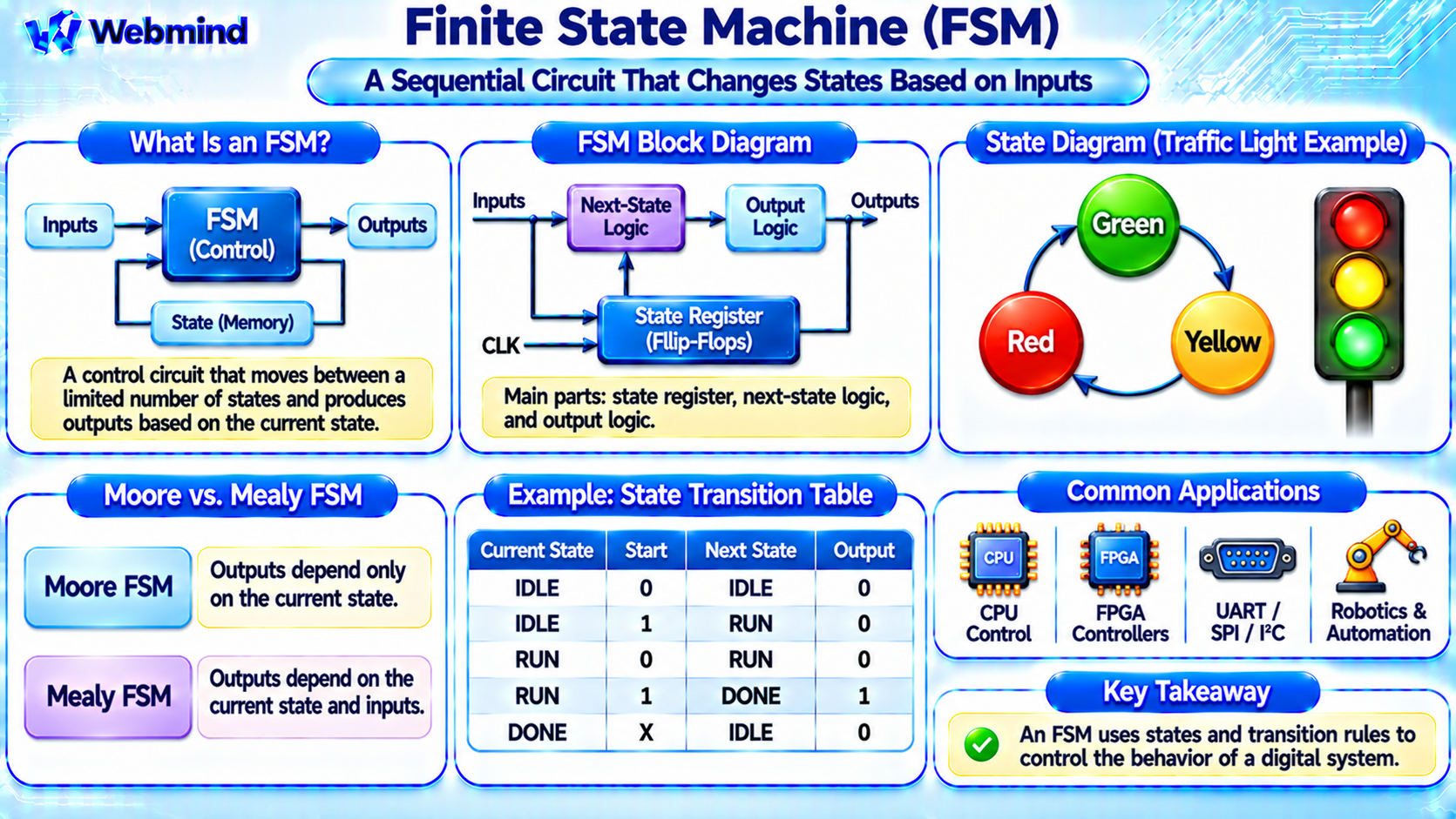
An FSM, or Finite State Machine, is a mathematical model and digital design technique used to describe systems that operate through a limited number of states.
It is widely used in digital electronics, CPUs, microcontrollers, FPGAs, ASICs, communication protocols, and embedded control systems.
Unlike a simple combinational circuit, whose outputs depend only on current inputs, a finite state machine remembers its current state and uses that information to determine what happens next.
For example, a traffic light controller can move between Green, Yellow, and Red states according to timing signals and control conditions.
FSMs provide a structured way to design, understand, and verify digital systems that perform sequences of operations.
How Does a Finite State Machine Work?
A finite state machine contains a defined set of states and rules that determine transitions between them.
At any particular moment, the system is in one state. Based on its current state and input conditions, it determines the next state.
A synchronous FSM typically updates its stored state at an active clock edge.
For example, a simple traffic light controller may follow this sequence:
GREEN → YELLOW → RED → GREEN
A timer determines when the controller moves from one state to another.
The current state determines which traffic light is active, while the transition conditions determine when the state changes.
This combination of state storage and transition logic is the foundation of an FSM.
Main Components of an FSM
A hardware finite state machine typically contains three major components.
State Register: Stores the current state, usually using flip-flops.
Next-State Logic: Determines the next state based on the current state and input signals.
Output Logic: Generates output signals according to the state and, depending on the FSM type, current inputs.
The state register provides memory, while the next-state and output logic implement Boolean functions.
For example, an FSM with four states may use a two-bit register to represent its states using binary encoding.
More complex state encoding methods may use additional flip-flops to improve timing or simplify logic.
What Is an FSM State?
A state represents a particular operating condition of a system.
For example, a vending machine controller might contain the states IDLE, WAITING, DISPENSE, and RETURN_CHANGE.
Each state represents a specific stage of operation.
When a customer inserts money, presses a button, or completes a transaction, the controller may transition to another state.
A state does not necessarily correspond to one physical component. It represents information about the system’s current behavior.
Well-designed FSMs use clearly defined states and transition conditions to avoid ambiguous or unexpected operation.
What Is a State Transition?
A state transition is the movement from one state to another.
Transitions occur when specified conditions are satisfied.
For example, consider a simple controller with three states:
IDLE: Wait for a Start signal.
RUNNING: Perform the required operation.
DONE: Indicate that the operation has completed.
When Start becomes active, the FSM transitions from IDLE to RUNNING at the relevant clock edge.
When the operation finishes, it transitions to DONE.
After receiving an acknowledgment, it returns to IDLE.
These transitions can be represented using a state diagram.
What Is a State Diagram?
A state diagram is a graphical representation of an FSM.
States are typically shown as circles or rounded shapes, while arrows represent transitions.
Each arrow may contain a condition that determines when the transition occurs.
For example:
IDLE → RUNNING → DONE → IDLE
The transition from IDLE to RUNNING may require Start = 1.
The transition from RUNNING to DONE may require Complete = 1.
State diagrams help engineers visualize control behavior before writing hardware description code.
They are also useful for reviewing design requirements and identifying missing transitions.
What Is a State Transition Table?
A state transition table describes FSM behavior using rows of current states, input conditions, next states, and sometimes outputs.
For example, consider a two-state controller with IDLE and ACTIVE states.
Current State = IDLE, Start = 0 → Next State = IDLE
Current State = IDLE, Start = 1 → Next State = ACTIVE
Current State = ACTIVE, Done = 0 → Next State = ACTIVE
Current State = ACTIVE, Done = 1 → Next State = IDLE
This table provides a precise description of the state transition rules.
EDA tools and hardware designers can use such information to implement and verify FSM logic.
Moore FSM vs. Mealy FSM
Finite state machines are commonly classified into two types.
Moore State Machine
In a Moore FSM, outputs depend only on the current state.
For example, a traffic light controller may produce a Green output whenever its current state is GREEN.
The output changes when the stored state changes.
Moore machines are often easier to understand and can provide stable state-controlled outputs.
Mealy State Machine
In a Mealy FSM, outputs depend on both the current state and current inputs.
For example, a communication controller may generate a response immediately when a particular input condition occurs while it is in a specific state.
Mealy machines can sometimes use fewer states or respond without waiting for another state transition.
However, their combinational outputs can change when inputs change, so timing and glitch behavior require careful consideration.
Neither type is universally better. The appropriate choice depends on the design requirements.
How Is an FSM Built from Logic Gates and Flip-Flops?
A synchronous FSM combines sequential storage with combinational logic.
The state register stores the current state using flip-flops.
Next-state logic calculates which state should follow.
Output logic produces the required control signals.
For example, a four-state FSM using binary state encoding may store its current state in two D flip-flops.
Combinational logic examines the current state bits and input signals to calculate the next two-bit state value.
At the next active clock edge, the flip-flops capture that value.
This creates a digital circuit that can remember its operating condition and follow a defined sequence.
What Is State Encoding?
State encoding determines how FSM states are represented using binary storage bits.
Several encoding methods are commonly used.
Binary Encoding: Uses a compact binary representation. An FSM with eight states can be represented using three state bits.
One-Hot Encoding: Uses one flip-flop per state. Typically, exactly one state bit is active at a time.
Gray Encoding: Assigns codes so that selected transitions change only one state bit, potentially reducing simultaneous switching activity.
Binary encoding can reduce register count, while one-hot encoding may simplify next-state logic and improve timing in some implementations.
The best encoding depends on the number of states, transition structure, target hardware, and design constraints.
FSMs in CPUs
CPUs use state-machine principles in many control functions.
For example, a simple multicycle processor may use an FSM to control instruction execution.
Possible control states include instruction fetch, instruction decode, execution, memory access, and result write-back.
The FSM determines which hardware operations occur during each stage.
Modern high-performance CPUs often use more sophisticated control structures, including pipelining, scheduling logic, and microcode.
Nevertheless, finite state machines remain important for managing instruction-related control, cache operations, communication interfaces, and other internal processor functions.
FSMs in FPGAs
FSMs are among the most important building blocks in FPGA development.
An FPGA uses Look-Up Tables (LUTs) to implement combinational logic and flip-flops to store the current state.
For example, an FPGA-based controller may monitor a sensor, activate a motor, wait for confirmation, and return to an idle state.
Each stage can be represented as an FSM state.
The synthesis tool maps the state register and Boolean logic into FPGA resources.
FSMs are commonly used in UART controllers, SPI interfaces, memory controllers, robotic systems, and digital communication hardware.
How Is an FSM Described in Verilog?
Hardware Description Languages such as Verilog and SystemVerilog provide a structured way to describe FSM behavior.
A common design uses separate logic for the state register and combinational next-state calculations.
The state register updates on the active clock edge.
Next-state logic examines the current state and inputs to determine the next state.
A case statement is often used to describe the behavior associated with each state.
For example, a controller may define the states IDLE, RUNNING, and DONE, with transitions controlled by Start and Complete signals.
SystemVerilog also supports enumerated types, which make state definitions more readable.
During synthesis, EDA tools convert the FSM description into flip-flops and logic gates or FPGA LUTs.
What Is FSM Reset?
An FSM generally needs a defined initial state.
A reset signal can place the state register into a known condition, such as IDLE.
Reset may be synchronous or asynchronous, depending on the implementation.
A synchronous reset takes effect at the relevant clock edge.
An asynchronous reset can change the stored state independently of the clock.
Designers must also consider what happens if the FSM enters an unused or invalid state encoding.
A robust design may include recovery behavior that returns the machine to a safe state.
This is especially important in industrial control, communication, and safety-related hardware.
Advantages of Finite State Machines
Structured Control: FSMs organize complex behavior into understandable states and transitions.
Predictable Operation: Clearly defined transition rules make system behavior easier to analyze.
Hardware Efficiency: FSMs can be implemented using flip-flops and combinational logic.
Easy Verification: State diagrams and transition tables provide useful references for testing.
Reusability: FSM structures can be reused in controllers and communication interfaces.
FPGA and ASIC Compatibility: FSMs can be synthesized into programmable or fixed-function digital hardware.
These advantages make FSMs a standard design technique in digital electronics.
Limitations of Finite State Machines
FSMs also introduce several design challenges.
State Explosion: Complex systems may require large numbers of states and transitions.
Timing Requirements: State registers and combinational logic must satisfy clock timing constraints.
Input Synchronization: Asynchronous external inputs may require synchronization before use.
Invalid States: Unused state encodings must be handled appropriately.
Design Complexity: Poorly organized state transitions can make an FSM difficult to maintain and verify.
Engineers address these challenges through hierarchical designs, careful state encoding, simulation, and formal verification.
Where Are FSMs Used?
Finite state machines are widely used in hardware and software systems.
CPUs: Instruction control and internal hardware coordination.
Microcontrollers: Embedded control applications and peripheral management.
FPGAs: Communication controllers, memory interfaces, and programmable automation.
ASICs: Specialized digital control circuits.
Communication Protocols: UART, SPI, I2C, and other protocol controllers.
Robotics: Motor sequences, sensor processing, and equipment control.
Industrial Automation: Machine sequencing and process control.
Software Systems: User interfaces, protocol handling, and workflow management.
Although software FSMs do not necessarily use dedicated flip-flop circuits, they follow the same underlying state-transition principles.
Conclusion
A Finite State Machine is a digital design model that represents system behavior using a limited number of states and defined transition rules.
In hardware, an FSM commonly combines a state register, next-state logic, and output logic.
Moore machines generate outputs based on the current state, while Mealy machines also consider current inputs.
FSMs are fundamental to CPUs, microcontrollers, FPGAs, ASICs, communication systems, and embedded controllers.
Understanding FSMs provides an important foundation for studying sequential logic, flip-flops, registers, Boolean algebra, Verilog, FPGA development, and digital hardware design.