Introduction
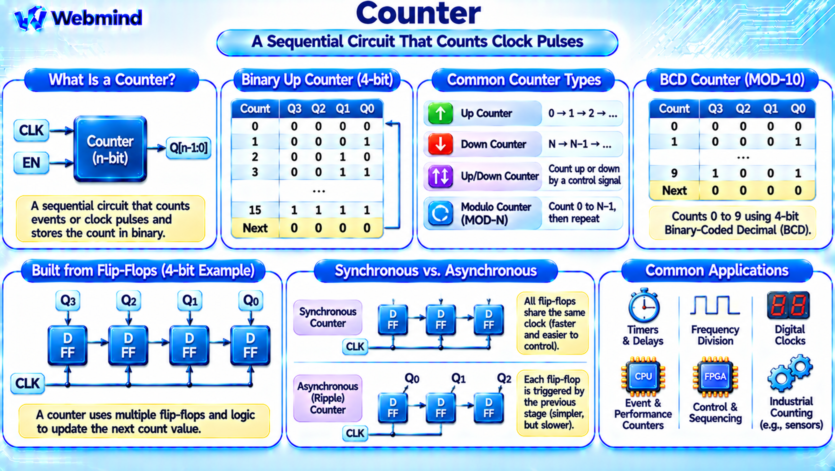
A counter is a sequential digital circuit that counts events or clock pulses and stores the current count as a binary number.
Counters are fundamental components of digital electronics and are widely used in CPUs, microcontrollers, FPGAs, ASICs, timers, and digital control systems.
Unlike combinational logic circuits, counters contain storage elements that retain information between clock events.
Most digital counters use flip-flops to store their current state.
For example, a four-bit binary counter can represent values from 0000 to 1111, corresponding to decimal numbers 0 through 15.
Counters are essential for measuring time, tracking events, generating frequencies, and controlling sequences of operations.
How Does a Digital Counter Work?
A digital counter changes its stored value in response to a triggering event, commonly a clock edge.
Consider a simple four-bit binary up counter.
Its output begins at 0000. After the first clock pulse, it becomes 0001. After the second pulse, it becomes 0010.
The sequence continues until the counter reaches 1111.
After the next pulse, a conventional four-bit modulo-16 counter returns to 0000.
The counting sequence is:
0000 → 0001 → 0010 → 0011 → 0100 → … → 1111 → 0000
Each clock event updates the stored binary value.
The maximum count depends on the number of bits and the counter’s design.
How Are Counters Built from Flip-Flops?
A counter is commonly constructed using flip-flops and combinational logic.
Each flip-flop stores one bit of the current count.
For example, a four-bit counter uses four storage bits, commonly labeled Q3, Q2, Q1, and Q0.
The combinational logic determines the next binary value based on the current state.
In a synchronous counter, all flip-flops receive the same clock signal and update together at the active clock edge.
Counters may use D, T, or JK flip-flops, depending on the circuit design.
Modern EDA tools can implement counter logic using optimized registers, logic gates, and dedicated arithmetic resources.
What Is an Up Counter?
An up counter increases its stored value by one for each counting event.
For example, a three-bit binary up counter follows this sequence:
000 → 001 → 010 → 011 → 100 → 101 → 110 → 111 → 000
The counter has eight distinct states because three bits can represent 2³ = 8 combinations.
Up counters are commonly used in event counting, timers, address generation, and digital measurement circuits.
Some counters include an Enable input so that counting occurs only when a specified condition is satisfied.
What Is a Down Counter?
A down counter decreases its stored value by one for each counting event.
For example, a three-bit binary down counter may follow:
111 → 110 → 101 → 100 → 011 → 010 → 001 → 000 → 111
Down counters are useful for countdown timers, remaining-event tracking, and digital control applications.
Some digital circuits use up/down counters that can increment or decrement according to a control signal.
For example, an up/down counter may count upward when UP = 1 and downward when UP = 0.
The exact control behavior depends on the implementation.
Synchronous vs. Asynchronous Counters
Digital counters are commonly divided into synchronous and asynchronous designs.
Synchronous Counter
In a synchronous counter, all flip-flops are driven by the same clock signal.
Combinational logic calculates the next state, and the flip-flops update together at the active clock edge.
Synchronous counters are widely used in modern digital systems because their timing behavior is relatively predictable.
Asynchronous Counter
An asynchronous counter, also called a ripple counter, uses the output of one flip-flop to trigger another.
The state changes propagate through the flip-flop chain.
This design can be simple, but propagation delays accumulate between stages.
As a result, intermediate output combinations may temporarily appear during transitions.
For high-speed synchronous systems, synchronous counters are generally preferred.
What Is a Modulo Counter?
A modulo counter, commonly called a MOD-N counter, cycles through N distinct states before repeating.
For example, a MOD-10 counter counts from 0 through 9 and then returns to 0.
Its sequence is:
0 → 1 → 2 → … → 9 → 0
A four-bit register can represent sixteen binary combinations, but a MOD-10 counter uses only ten counting states.
Additional logic controls the transition back to zero.
Modulo counters are used in digital clocks, frequency dividers, timers, and numerical displays.
What Is a Binary-Coded Decimal Counter?
A Binary-Coded Decimal (BCD) counter represents decimal digits using four-bit binary codes.
A BCD counter typically cycles through the values 0000 to 1001, representing decimal 0 through 9.
After 1001, it returns to 0000.
The binary combinations 1010 through 1111 are not used as valid decimal digits in standard BCD counting.
BCD counters are useful in systems that display decimal numbers, such as digital clocks, electronic instruments, and counting devices.
Multiple BCD counter stages can be connected to represent larger decimal values.
How Do Counters Divide Clock Frequency?
Counters are often used as frequency dividers.
A T flip-flop configured to toggle on every active clock edge produces an output that changes state once per clock cycle.
For a periodic input clock, its output frequency is half the input frequency.
By cascading suitable counting stages, a circuit can generate frequencies divided by powers of two.
For example, a four-bit binary counter driven by a 16 MHz clock can produce output bits with frequencies of approximately 8 MHz, 4 MHz, 2 MHz, and 1 MHz.
These are logical frequency relationships under normal operating conditions.
In practical FPGA and ASIC design, generated clocks require careful timing management.
Counter-derived enable signals are often preferable to using ordinary logic outputs as new clock signals.
Counters in CPUs and Microcontrollers
Counters perform many functions inside processors and embedded systems.
Timers: Count clock cycles to measure time intervals.
Event Counters: Track external or internal events.
Performance Counters: Record processor events such as instructions retired, cache misses, or clock cycles.
Program Control: Internal counters may track repeated operations or implementation-specific sequences.
Communication Interfaces: Counters help control timing in serial communication and digital protocols.
Microcontrollers often contain hardware timer/counter peripherals that operate independently of the CPU’s main instruction execution.
These peripherals may generate interrupts, measure pulse widths, or control Pulse-Width Modulation (PWM) signals.
What Is a Timer vs. a Counter?
Timers and counters are closely related.
A counter tracks the number of events that have occurred.
A timer uses a known clock frequency to measure elapsed time or generate time intervals.
For example, if a counter receives a clock running at 1 MHz, each clock cycle represents one microsecond.
After 1,000 clock cycles, one millisecond has elapsed.
A microcontroller timer can use this relationship to generate periodic interrupts or delays.
In practice, many hardware peripherals combine timer and counter capabilities in the same circuit.
Counters in FPGAs
Counters are among the most common introductory FPGA designs.
An FPGA counter uses flip-flops to store the current binary value and configurable logic to calculate the next count.
For example, a 32-bit counter can increment on each rising edge of a system clock.
Its output can be used to track elapsed cycles, generate periodic enable pulses, or control a digital state machine.
FPGA counters can also include reset, enable, load, and direction-control functions.
Synthesis tools typically implement counters using registers and dedicated arithmetic carry-chain resources where available.
Understanding counters is an important step toward learning practical FPGA development.
How Is a Counter Described in Verilog?
A simple binary counter can be described using a clocked Verilog process.
For example, the statement:
always @(posedge clk) count <= count + 1'b1;
describes a register that increments its value at every rising clock edge.
The width of count determines how many binary values it can represent.
For a four-bit unsigned counter, the value wraps from 15 back to 0.
Practical counter designs often include reset and enable signals.
During synthesis, an EDA tool converts the description into flip-flops and the required incrementing logic.
The same basic design can be implemented in an FPGA or ASIC.
What Is Counter Overflow?
Counter overflow occurs when a counter exceeds the maximum value its storage width can represent.
For an unsigned n-bit binary counter, the maximum value is:
2ⁿ − 1
For example, an 8-bit unsigned counter can represent values from 0 through 255.
If it increments while holding 255, the result wraps to 0 when arithmetic is limited to eight bits.
This is called wraparound behavior.
Some counter designs instead stop at a maximum value, reload a programmed value, or generate an overflow signal.
Engineers must select the appropriate behavior for the intended application.
What Is a Ring Counter?
A ring counter is a specialized sequential circuit based on a shift register.
A single active bit circulates through a group of storage elements.
For example, a four-bit ring counter may follow:
0001 → 0010 → 0100 → 1000 → 0001
The circuit repeats after four states.
Ring counters are useful in sequence generation, control logic, and selected timing applications.
A related design called a Johnson counter uses an inverted feedback signal and can produce a larger sequence of states from the same number of flip-flops.
These counters are alternatives to conventional binary counters for specific applications.
What Is Counter Propagation Delay?
Real counters do not update instantaneously.
Each flip-flop and logic gate introduces propagation delay.
In asynchronous ripple counters, the delay can accumulate as state changes propagate through multiple flip-flops.
In synchronous counters, combinational logic must calculate the next state before the active clock edge, and timing constraints must be satisfied.
Large counters may require optimized carry chains or other circuit structures to operate at high frequencies.
Static Timing Analysis (STA) helps engineers verify that a counter can operate reliably at its required clock speed.
Where Are Digital Counters Used?
Counters appear throughout modern electronics.
CPUs: Performance monitoring, event tracking, and internal control functions.
Microcontrollers: Hardware timers, PWM generation, event counting, and interrupt scheduling.
FPGAs: Clock-cycle tracking, state machine control, frequency division, and digital interfaces.
ASICs: Specialized timing, counting, and control circuits.
Digital Clocks: Count time intervals and generate clock display values.
Communication Systems: Track transmitted data units, timing intervals, and protocol events.
Industrial Automation: Count sensor pulses, motor rotations, and production events.
Their ability to track changes over time makes counters essential in digital systems.
Conclusion
A counter is a sequential digital circuit that stores a binary value and updates it in response to clock pulses or other events.
Common counter types include up counters, down counters, synchronous counters, asynchronous counters, modulo counters, and BCD counters.
Counters are usually built using flip-flops and combinational logic, allowing them to measure events, generate timing signals, and control digital operations.
They are widely used in CPUs, microcontrollers, FPGAs, ASICs, communication systems, and industrial electronics.
Understanding counters provides an important foundation for studying flip-flops, registers, sequential logic, clock signals, Verilog, FPGA development, and digital circuit design.